GE Multilin T60 Transformer Protection System 2-3
2 PRODUCT DESCRIPTION 2.1 INTRODUCTION
2
2.1.2 ORDERING
a) OVERVIEW
The T60 is available as a 19-inch rack horizontal mount or reduced-size (¾) vertical unit and consists of the following mod-
ules: power supply, CPU, CT/VT, digital input and output, transducer input and output, and inter-relay communications.
Each of these modules can be supplied in a number of configurations specified at the time of ordering. The information
required to completely specify the relay is provided in the following tables (see chapter 3 for full details of relay modules).
Order codes are subject to change without notice. CPU modules 9G, 9H, 9L, and 9M are obsolete. See
http://www.gedigitalenergy.com/multilin/order.htm for the latest ordering options.
The order code structure is dependent on the mounting option (horizontal or vertical) and the type of CT/VT modules (regu-
lar CT/VT modules or the HardFiber modules). The order code options are described in the following sub-sections.
b) ORDER CODES WITH TRADITIONAL CTS AND VTS
The order codes for the horizontal mount units with traditional CTs and VTs are shown below.
The following features are not available when the T60 is ordered with three CT/VT modules: breaker arcing current,
load encroachment, and breaker failure.
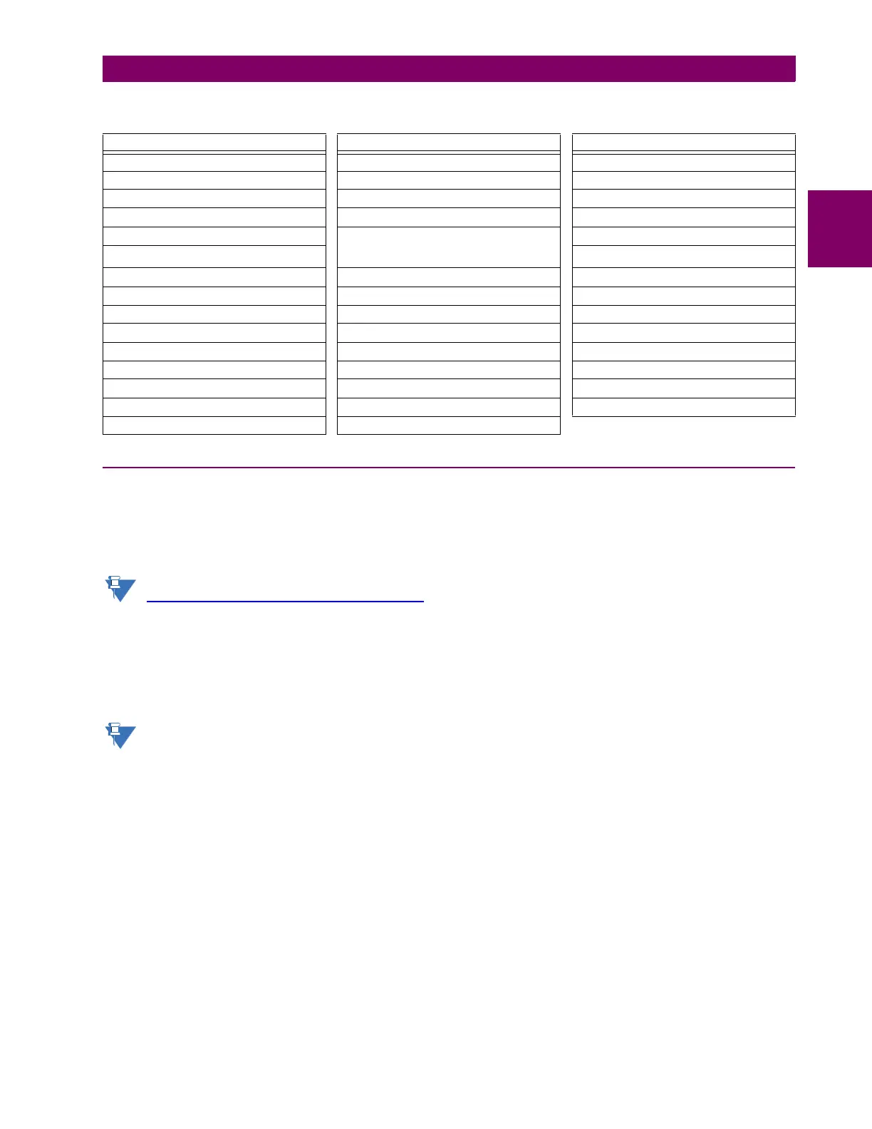
Table 2–2: OTHER DEVICE FUNCTIONS
FUNCTION FUNCTION FUNCTION
Breaker arcing current I
2
t FlexElements™ (16) Time synchronization over SNTP
Breaker control FlexLogic™ equations Transducer inputs and outputs
Breaker flashover IEC 61850 communications (optional) Transformer aging factor
Breaker restrike Load encroachment Transformer hottest-spot temperature
Contact inputs (up to 96) Metering: current, voltage, power, power
factor, energy, frequency,
harmonics, THD
Transformer loss-of-life
Contact outputs (up to 64) Trip bus
Control pushbuttons Modbus communications User-definable displays
Data logger Modbus user map User-programmable fault reports
Digital counters (8) Non-volatile latches User-programmable LEDs
Digital elements (48) Non-volatile selector switch User-programmable pushbuttons
Direct inputs and outputs (32) Oscillography User-programmable self-tests
Disconnect switches Pilot Scheme (POTT) Virtual inputs (64)
DNP 3.0 or IEC 60870-5-104 protocol Remote RTD inputs Virtual outputs (96)
Ethernet Global Data protocol (optional) RTD inputs VT fuse failure
Event recorder Setting groups (6)