GE Multilin T60 Transformer Protection System 3-31
3 HARDWARE 3.3 DIRECT INPUT/OUTPUT COMMUNICATIONS
3
OBSERVING ANY FIBER TRANSMITTER OUTPUT MAY CAUSE INJURY TO THE EYE.
3.3.2 FIBER: LED AND ELED TRANSMITTERS
The following figure shows the configuration for the 7A, 7B, 7C, 7H, 7I, and 7J fiber-only modules.
Figure 3–32: LED AND ELED FIBER MODULES
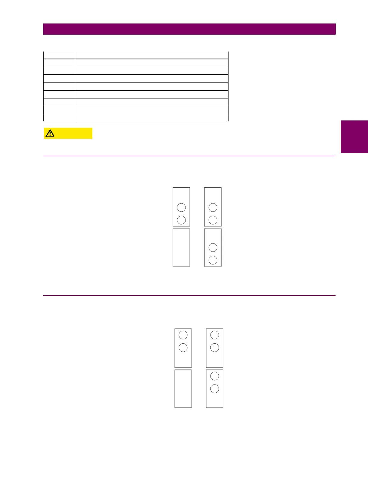
3.3.3 FIBER-LASER TRANSMITTERS
The following figure shows the configuration for the 72, 73, 7D, and 7K fiber-laser module.
Figure 3–33: LASER FIBER MODULES
7N Channel 1: RS422, channel 2: 1300 nm, single-mode, ELED
7P Channel 1: RS422, channel 2: 1300 nm, single-mode, laser
7Q Channel 1: G.703, channel 2: 1300 nm, single-mode, laser
7R G.703, 1 channel
7S G.703, 2 channels
7T RS422, 1 channel
7V RS422, 2 channels, 2 clock inputs
7W RS422, 2 channels
Table 3–4: CHANNEL COMMUNICATION OPTIONS (Sheet 2 of 2)
MODULE SPECIFICATION
Module: 7A / 7B / 7C 7H / 7I / 7J
Connection Location: Slot X Slot X
1 Channel 2 Channels
RX1 RX1
RX2
TX1 TX1
TX2
831719A2.CDR
Module:
Connection Location:
73/ 7K
Slot X
72/ 7D
Slot X
1 Channel 2 Channels
RX1 RX1
RX2
TX1 TX1
TX2
831720A3.CDR