Components and Functions (Theory)
5-44 Vivid E80/E90/E95 – Service Manual
GC091052
Rev. 3
General description (continued)
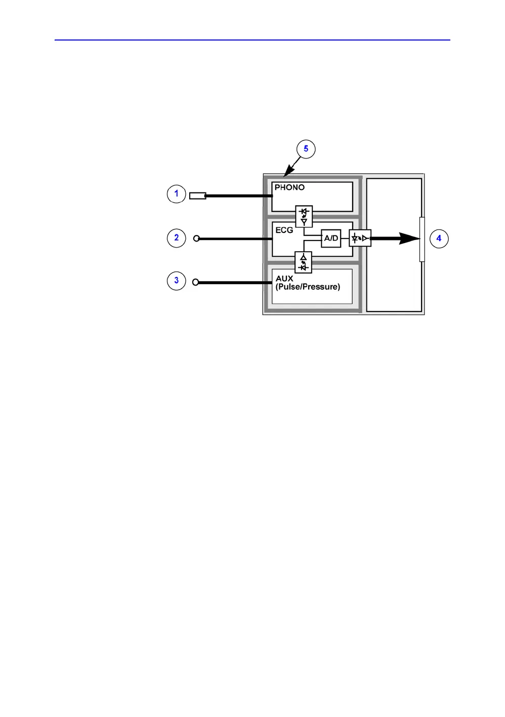
The three inputs are separately isolated due to safety
requirements.
Figure 5-24. Patient I/O - block diagram
The patient leads for ECG can be rotated by software (i.e. it is
possible to change between Lead I, II and III by pushing a
button).
The module extracts respiration from the ECG input signals.
The scanned image that is displayed, is synchronized with the
ECG, respiration and PHONO traces. In M-Mode or Doppler, the
traces are synchronized to that particular mode's sweep. The
operator can control the gain, the position and the sweep rate of
the traces using the assignable controls.
AUX is capable of handling a Pressure/Pulse signal.
Patient I/O location
The Patient I/O is located at the front of the BEP with the
connector panel available from the front of the Ultrasound
system.
For illustration, see: Figure 5-23.
1. Phono
2. ECG
3. AUX (Pressure/Pulse)
4. Digital Trace Data, USB2 to BEP