D
IRECTION FR091521, REVISION 1 VIVID S60N/VIVID S70N BASIC SERVICE MANUAL
8-136 Section 8-5 - Electronic Cage Components - Replacement Procedures
PRELIMINARY
8-5-19 Fan for Cabinet Cage Assembly Replacement Procedure
8-5-19-1 Tools
Phillips screwdriver.
8-5-19-2 Time Required
20 mins
8-5-19-3 Preparation
Shut down the Vivid™ S60/Vivid™ S70 ultrasound unit, as described in Power Shut Down on page 4 - 7.
8-5-19-4 Fan for Cabinet Cage Assembly Removal Procedure
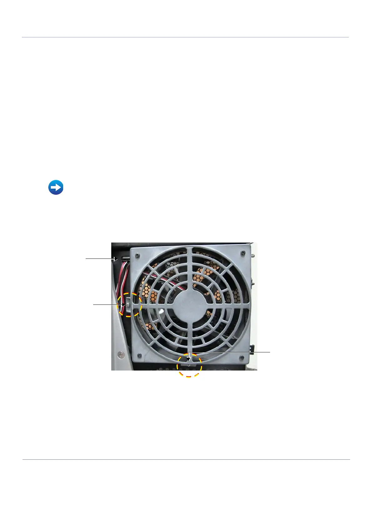
The fan (see Figure 8-165 below) is located at the rear of the scanner.
1) Remove the following covers: right side, DVD, front, right rear:
2.) Disconnect the Fan cable as indicated in Figure 8-165 below.
3.) Loosen and remove the two securing screws as indicated in Figure 8-165, above.
4.) Remove the fan.
Refer to Table 9-17 on page 9-16.
• Right Side Cover Removal Procedure on page 8 - 10
• DVD Cover Removal Procedure on page 8 - 11
• Front Cover Removal Procedure on page 8 - 16
• Right Rear Cover Removal Procedure on page 8-20
Figure 8-165 Fan for Cabinet Cage Assembly
Disconnect cable
Securing screw
Securing screw
 Loading...


