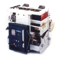
WavePro™ low voltage power circuit breakers have been test-
ed with Ferraz-Shawmut current limiting fuses. Table 33.1
lists the catalog numbers of the fuses used on the circuit
breakers (integrally fused) and in separately mounted fuse
roll-out elements.
Table 33.1 WavePro current limiting fuse catalog numbers
Fuse Ratings Ferraz-Shawmut Fuse Silver Fuse
Breaker Mounted Fuses Catalog Number Catalog Number
300A - J A4J300
350A - J A4J350
400A - J A4J400
450A - J A4J450
500A - J A4J500
600A - J A4J600
800A - L A4BY800 A4BQ800
1000A - L A4BY1000BG A4BQ1000BG
1200A - L A4BY1200BG A4BQ1200BG
1600A - L A4BY1600BG A4BQ1600BG
2000A - L A4BY2000 A4BQ2000
2500A -L (Silver) A4BQ2500GE
Fuses for Roll-out Elements
2000A - L A4BY2000-55BA
2500A - L A4BY2500-55BA
3000A-L A4BY3000-55BA
4000A - L A4BY4000-55BA
5000A - L A4BY5000-55BA
Welder Limiters
800A A4BX800
1000A A4BX1000BG
1600A A4BX1600BG
2000A A4BX2000
Breaker Weights and Fuse Ratings (cont.)
Breaker Frame Size Watts Loss
800 160
1600 325
2000 508
3200 830
4000 1050
5000 1650
Watts loss values shown are for 100% current values. Add fuse
watts loss to breaker watts loss if breaker has integral fusing. To
convert watts loss to BTU/hr, multiply watts by 3.42. Watts loss for
lower current values may be estimated by the following formula:
W
e
=W
FL
(I/I
FL
)
2
where W
e
= estimated watts loss at load current
W
FL
= estimated watts loss at full load current (100%
of frame rating) see table above
I = load current
I
FL
= full load current (100% frame rating)
Table 33.3 Derating factor for systems with power factors lower than
test values
Temperature derating factors
The continuous current rating of WavePro breakers is based
on their use in an enclosure at 40° C ambient temperature
and 105° C maximum breaker temperature for Class A insu-
lation. Continuous current ratings of WavePro breakers must
be derated for ambient temperatures above 40° C.
(Trip unit
ambient is limited to 70° C.)
Table 33.4 Continuous derating factors
Altitude correction factors
When applying low voltage power circuit breakers at altitudes
greater than 6,600 feet, their continuous current rating must
be modified because a higher temperature use will be experi-
enced for a given current rating. The voltage ratings must also
be modified because of the lower dielectric strength of the air.
The short-time and short-circuit current ratings are not
affected by altitude. However, the short-circuit current ratings
shall not exceed that of the voltage class before derating.
Table 33.5 Altitude correction factors (as listed in ANSI C37.13)
Table 33.6 Insulation values (Dielectric test)
Table 33.7 Operating time (Same for all frame sizes)
kV
Breaker 2.2
Control Wiring 1.5
Spring Charging Motor 0.9
Ambient temperature (°C) Derating factor
40 1.00
45 0.95
50 0.89
55 0.84 ➀
60 0.77
65 0.71
70 0.63
Altitude Rating correction factor
Meters Feet Continuous current Voltage
2000 6600 (and below) 1.00 1.00
2600 8500 0.99 0.95
3900 13000 0.96 0.80
Close
Time from energizing closing Electrically 5 Cycles
circuit until contacts touch operated
Open
Maximum clearing time With instantaneous 3 Cycles
overcurrent trip
With shunt trip 3.5 Cycles
➀ Trip unit maximum
Application Information
Power factors lower than test values affect the circuit breaker’s
short-circuit current rating. The test circuit X/R ratio and
power factor required by ANSI C37.13 is 6.6 and 15%
for unfused breakers and 4.9 and 20% for fused breakers.
Derating factors for breaker
System short-circuit System short-circuit current rating
power factor (%) X/R ratio Unfused Fused
20 4.90 1.000 1.000
15 6.60 1.000 0.938
12 8.27 0.966 0.902
10 9.95 0.938 0.875
8.5 11.72 0.920 0.847
7 14.25 0.902 0.826
5 20.00 0.875 0.794
Suffix BG provides notched blade rejection
Suffix GE provides offset blade for breaker mounting
Suffix 55BA provides milled blade rejection
Table 33.2 WavePro breaker estimated heat loss (per breaker – 3-pole)
33
Fuse Rating @ Watts Loss Fuse Location
Continuous Amps (3 Fuses)
1000A @ 800A 136 Fuse on breaker
1600A @ 800A 76 Fuse on breaker
2500A @ 1600A 205 Fuse on breaker
2000A @ 1200A 142 Fuse on breaker
2500A @ 2000A 303 Fuse rollout
4000A @ 3200A 445 Fuse rollout
5000A @ 4000A 574 Fuse rollout
6000A @ 5000A 990 Fuse rollout