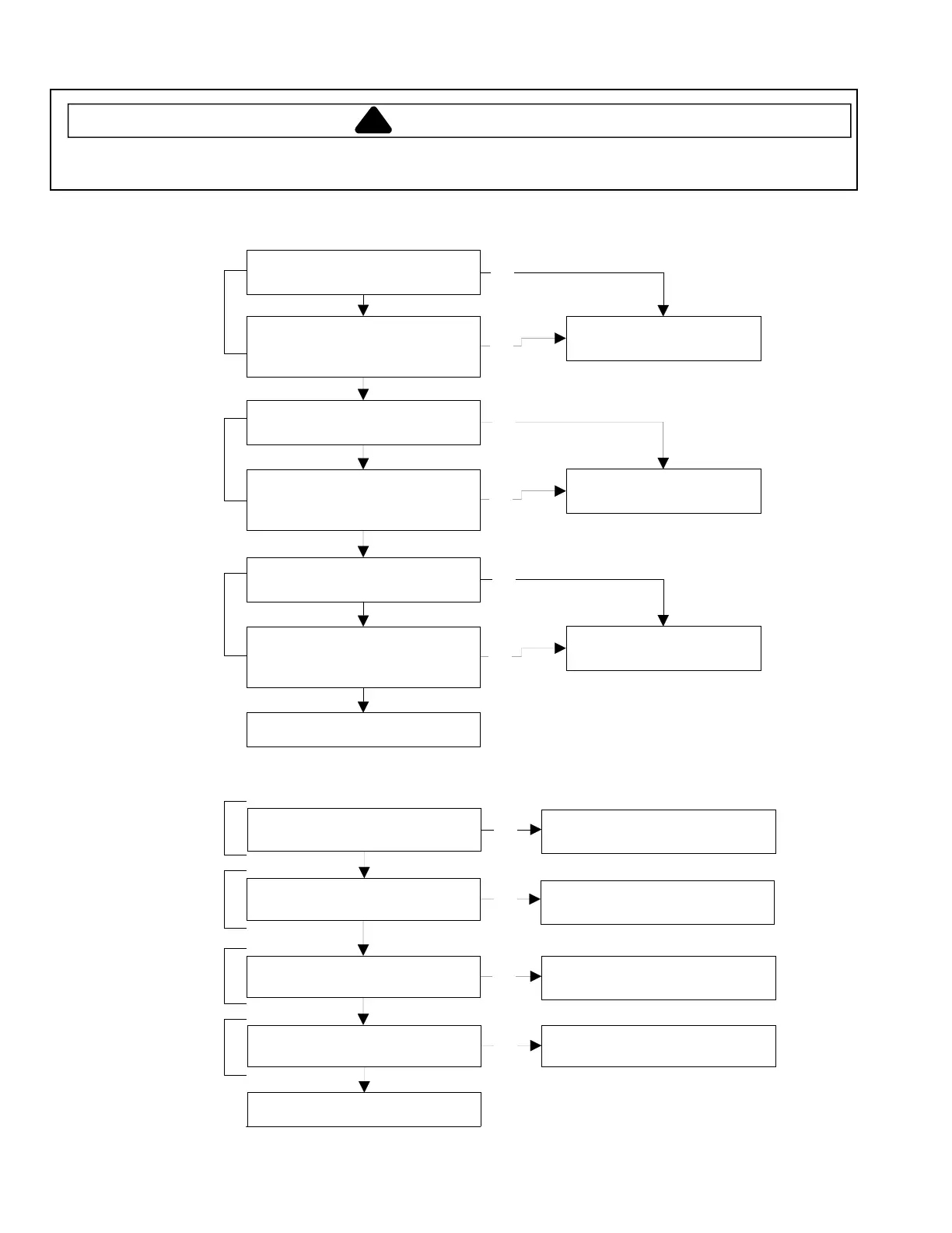
Internal Motor Diagram and Schematic
!
WARNING
To avoid risk of electrical shock, personal injury, or death, disconnect power to washer before servicing, unless
testing requires it.
10
Continuity exists between switch
terminal
R
and Red wire.
Manually depress actuator.
Continuity broken between
switch terminal
R
and Red wire.
Continuity exists between switch
terminal
P
and Red wire.
Manually depress actuator.
Continuity broken between
switch terminal
P
and Red wire.
Inoperative start switch.
Replace switch.
Inoperative high speed
switch. Replace switch.
Continuity broken between
switch terminal
P
and Violet wire.
Manually depress actuator.
Continuity exists between switch
terminal
P
and Violet wire.
Inoperative low speed
switch. Replace switch.
Motor switch checks OK.
NO
YES
YES
YES
YES
YES
YES
NO
NO
NO
NO
NO
Start
Terminals
High Speed
Terminals
Low Speed
Terminals
One or Two Speed Motors
4-5 ohms between Brown wire
and Red wire.
1-2 ohms between Blue wire and
Yellow wire.
1-2 ohms between Yellow wire
and Violet wire.
Continuity exists between Yellow
wire and White wire.
All motor windings checks OK.
Inoperative start winding.
Replace motor.
Inoperative high speed winding.
Replace motor.
Inoperative low speed winding.
Replace motor.
Inoperative common lead.
Replace motor.
Start
Winding
High Speed
Winding
Low Speed
Winding
Protector
NO
NO
NO
NO
YES
YES
YES
YES
 Loading...