Installation
DANGER
HAZARDOUS VOLTAGE
(Can Cause Severe Injury or Death)
Turn OFF all power before installation, adjustment, or removal of transfer switch or any of its components.
Power Connections
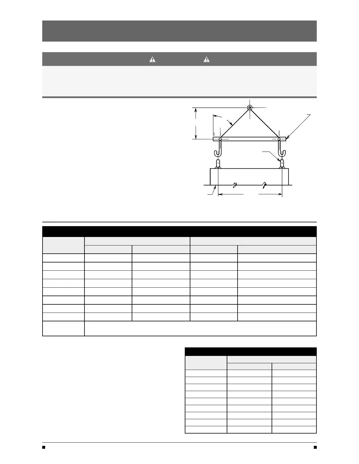
SPREADER BAR
GE Zenith transfer switches are supplied with UL listed
45°
solderless screw type terminals as standard for the
H
Source 1, Source 2 and Load power connections.
Table 1 lists the number and sizes of cable lugs supplied
as standard for each switch amp rating.
Connect the Source 1, Source 2, and Load conductors
LIFTING EYES
to the clearly marked terminals on the transfer switch.
Remove sur
face oxides from cables by cleaning with a
wire brush. Verify that all connections are correct before
tightening the lugs. All cable lug connections must be
tightened to the proper torque values as shown in
Table 2.
NOTE
: Do not run cables or wiring behind
CABINET
D
front-connected transfer switches.
NOTE
: When lifting the switch using a spreader bar,
height H must be equal to half of distance D.
Figure 1
Power Connections: Screw Type Terminals for External Power Connections
Switch Size
(Amps)
Source 1, Source 2 & Load Terminals Neutral Bar (When Required)
Cable Per Pole Range of Wire Sizes No. of Cables Range of Wire Sizes
40 1 #8 AWG to 1/0 3 #8 AWG to 1/0
80 1 #8 AWG to 1/0 3 #8 AWG to 1/0
100 1 #8 AWG to 1/0 3 #8 AWG to 1/0
150 1 #8 AWG to 3/0 3 #8 AWG to 300 MCM
200, 225, 2500 1 #6 AWG to 250 MCM 3 #6 AWG to 300 MCM
260, 300*, 400
1
#4 AWG to 600 MCM 3 #4 AWG to 300 MCM
600 2 #2 AWG to 600 MCM 8 #2 AWG to 600 MCM
800, 1000, 1200 4 #2 AWG to 600 MCM 12 #2 AWG to 600 MCM
1600, 2000
2600, 3000, 4000
Line, Load and Neutral terminals are located in the rear of switch
and arranged for bus bar locations
Table 1
Engine Start
Control Connections
Engine-start control wires connect to control terminals
beside the Entelli-Switch 250. Engine start terminals are
indicated by a schematic symbol (the symbol indicates
the contact state for a de-energized normal source).
Figure 2 shows the engine-start contacts.
Make all other necessary control connections to the
control panel terminal blocks per the schematics
supplied with the A
TS.
NOTE: All control wires (18-12 AWG) must be
torqued to 19 in/lbs.
Tightening Torque for Lugs
Socket Size
Across Flats
Torque
Lb. - In.
Lb. - Ft.
1/8 45
4
5/32
100
8
3/16 120
10
7/32
150
12
1/4
200 17
5/16 275
23
3/8
375
31
1/2
500 42
9/16
600 50
Table 2
ZTS / ZTSD Operation and Maintenance Manual (71R-3000)
GE Zenith Contr
ols 2

 Loading...