D
GB
F
E
19
09726-06.2018-DGbF
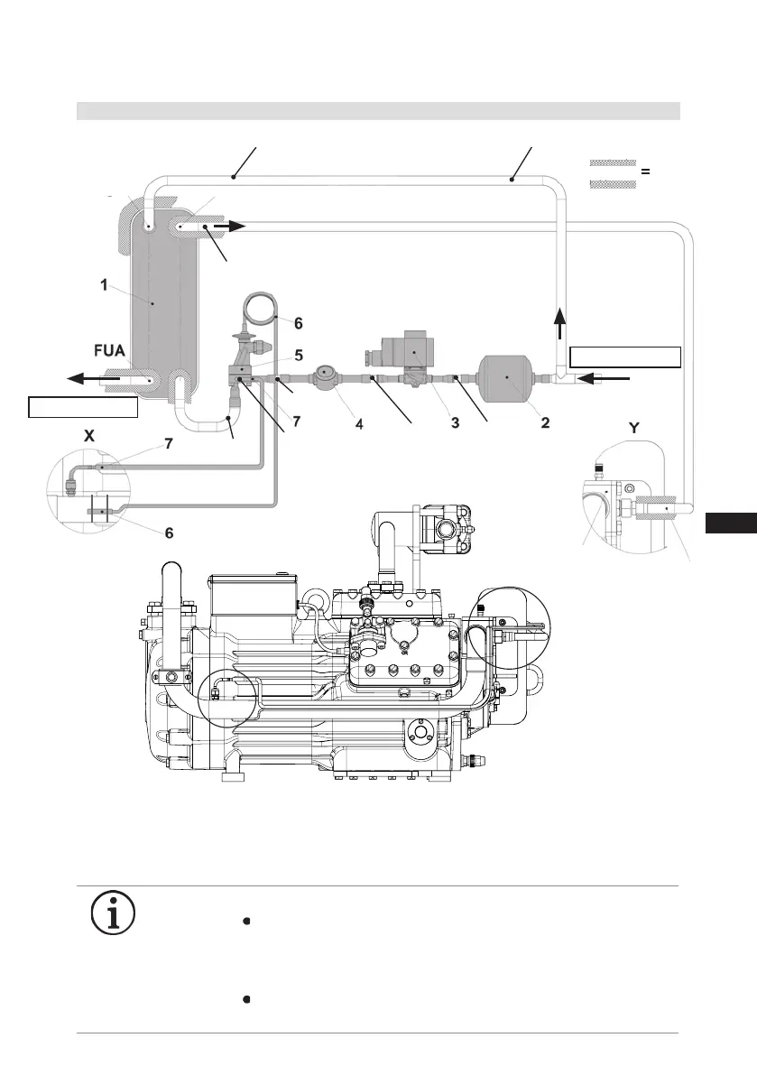
5| Compressor assembly
1 Liquidsubcooler 5 Expansion valve FUA Liquidsubcooler,
2 Filter drier 6 Temp. sensor expansion valve Outlet
3 Solenoid valve 7 Pressure compensation connection FUE Liquidsubcooler,
4 Sight glass Inlet
Dia.16 mm
Dia.6 mm
Dia.12 mm
Dia.12 mm
Dia.12 mm
FUE
Fig.23
5.4 Installationexample,liquidsubcoolerwithaccessories
GB
INFO
General notes:
Sensor lines, wires, etc. should not be attached with cable
binders directly to pipes or frames; otherwise, the thin pipes
may be worn through. It is better to run them through spiral
protective tubes.
If the compressor will be set up outside, UV-resistant materials
should be used.
X
Y
Line A
to the evaporator
Dia. 16 mm
Heat
insulation
Line B
Dia. 16 mm
Dia. 16 mm
from the receiver
Line B
Intermediate pressure
chamber MP

 Loading...

