10
D
GB
F
E
09706-09.2013-DGbFEI
?
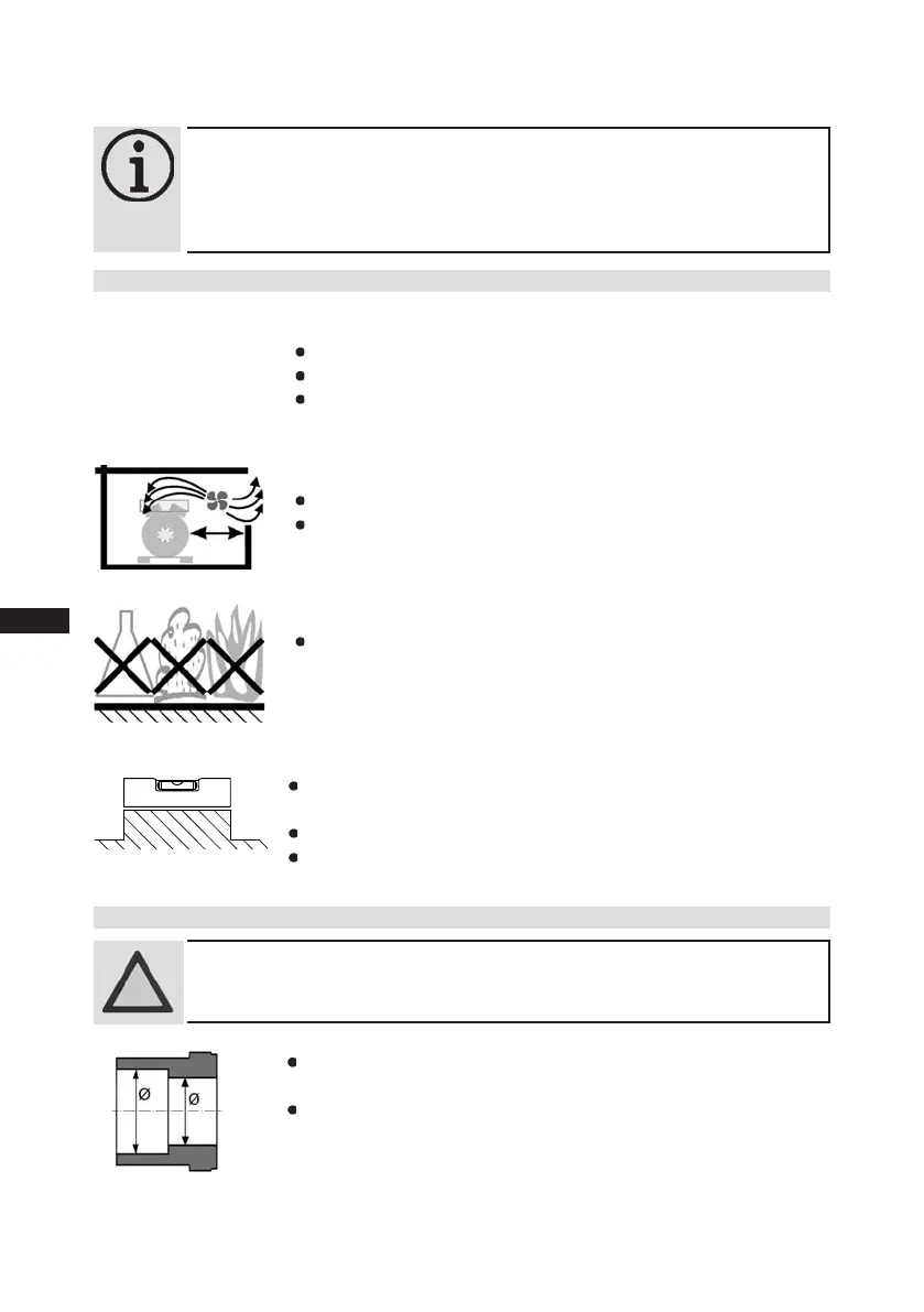
4.1 Setting up
Setuponanevensurfaceorframewithsufcientload-
bearing capacity.
Single compressor preferably on vibration damper.
Duplex and parallel circuits always rigid.
Use transport eyelet.
Do not lift manually!
Use lifting gear!
Provideadequateclearanceformaintenancework.
Ensureadequatecompressorventilation.
Do not use in a corrosive, dusty, damp atmosphere or a
combustible environment.
Fig. 8
Fig. 9
Fig. 10
Fig. 11
ATTENTION! Superheating can damage the valve.
Remove the pipe supports from the valve for soldering.
Only solder using inert gas to inhibit oxidation products (scale).
4.2 Pipe connections
The pipe connections have graduated inside diameters so that pipes with
standart millimetre and inch dimensions can be used.
The connection diameters of the shut-off valves are rated for maximum
compressor output. Theactualrequiredpipecrosssectionmustbe
matched to the output. The same applies for non-return valves.
Fig. 12: graduated
internal diameter
F
E
D
C
B
A
1
2
3
4
F
E
D
C
4
3
2
1
A
B
Tol.-Ang. DIN ISO 2768-mK
Ra Rz
Maß
Passung
Freigabe
Alternativbezug:
Baumustergeprüft
Teil inaktiv
Lieferantenzeichnung
-
-
K.-Auftrag:
PL:
Zeichnung ungültig
Entwicklungsstand
Teil keine Serie
120
400
±0.5
über 0.5
bis 6
Benzstraße 7 - 72636 Frickenhausen - Germany - www.bock.de
-
-
Unbemaßte Radien:
-
Diese Zeichnung ist unser Eigentum!
Sie darf ohne unsere Genehmigung weder nach-
gebildet, vervielfältigt, oder Dritten Personen zu-
gänglich gemacht werden. Der Nachbau nach
dieser Zeichnung, oder an Hand der nach dieser
Zeichnung hergestellten Gegenstände durch den
Abnehmer oder Dritte ist nicht gestattet.
Wir behalten uns alle Rechte, gemäß DIN ISO 16016
an dieser Zeichnung vor.
Bearb.
Datum
Änderungs-Nr.
Werkstoff:
Ausgangsteil, bzw. Rohteil:
-
-
Gepr.
Name
Datum
19.04.
Werkstückkanten
DIN ISO 13715
Ersatz für:
Ersetzt durch:
Erstellt
2010
Geprüft
-
Kurz
Zone
1/x
Oberflächenbehandlung / Härte:
-
Blatt:
Änderungsbeschreibung
400
Benennung:
±0.8
1000
30
6
-
±0.3
120
30
±0.2
Zeichn.-Nr. Teile-Nr.
Oberflächenangaben ISO 1302
x.xxxx-xxxxx.x
Zust.
Gußtoleranzen:
Gewicht: (kg)
±0.1
Maßstab:
1:1
Wasserwaage
für Indesign
Der Lieferant muß sicherstellen, dass die Ware in
einwandfreiem Zustand angeliefert wird (Korrosions-
schutz, Verpackung für sicheren Transport).
Rz 25
Rz 160
s
25
z
y
x
w
u
t
0,05
Rz 1,6
0,3
0,7
1,6
2
Rz 16
6,3
Rz 63
Rz 6,3
Rz 12,5
F:\user\kurz\3D Sachen\3D Teile\Zeichnungen\Wasserwaage
4| Compressor assembly
INFO! Newcompressorsarefactory-lledwithinertgas(3barnitrogen).
Leave this service charge in the compressor for as long as possible
and prevent the ingress of air.
Check the compressor for transport damage before starting any
work.

 Loading...