D
GB
F
E
27
09706-09.2013-DGbFEI
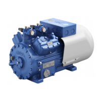
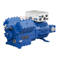
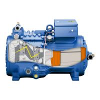
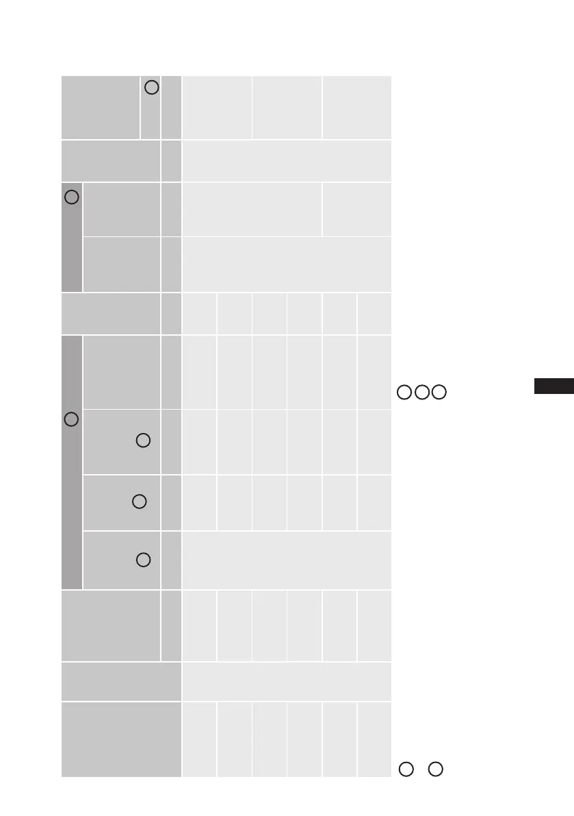
8| Technical data
Type
No. of
cylin-
ders
Displace-
ment
50/60Hz
(1450 / 1740
rpm)
Electrical data
Weight
Connections Oil
charge
Sound
pressure
level
Voltage Max.
Operating
current
PW 1 + 2
Max. power
consump-
tion
Starting
current
(rotorlocked)
PW 1 / PW 1 + 2
Dis-
charge
line
DV
Suction
line
SV
m
3
/h A kW A kg mm (inch) mm (inch) Ltr. d B( A)
HG7/1620-4
6
140,6 / 168,8 76 38,7 227 / 340 278
42 (1
5
/
8
)
54 (2
1
/
8
)
4,5
78 / 78 / 77
HG7/1620-4 S 140,6 / 168,8 83 46,3 268 / 373 299
HG7/1860-4 161,4 / 193,7 83 44,6 268 / 373 296
79 / 79 / 78
HG7/1860-4 S 161,4 / 193,7 98 53,3 343 / 494 292
HG7/2110-4 183,6 / 220,3 98 51,2 343 / 494 289
64 (2
5
/
8
) 80 / 80 / 79
HG7/2110-4 S 183,6 / 220,3 115 60,5 344 / 500 297
1
2
3
2
4
380-420 V Δ/YYY - 3 - 50 Hz PW
440-480 V Δ/YYY - 3 - 60 Hz PW
PW = Part Winding
Winding ratio : 60% / 40%
L / M / H
5
Tolerance (± 10%) relative to the mean value of the voltage range.
Othervoltagesandtypesofcurrentonrequest.
-Thespecicationsformax.powerconsumptionapplyfor50Hzoperation.
For60Hzoperation,thespecicationshavetobemultipliedbythefactor
1.2. The max. working current remains unchanged.
- Take account of the max. operating current / max. power consumption for
design of fuses, supply lines and safety devices. Fuse: Consumption
category AC3
1
2
Allspecicationsarebasedontheaverageofthevoltagerange
For solder connections
L = low temperature (-35 / 40 °C), M = normal cooling (-10 / 45 °C),
H = air conditioning (5 / 50°C)
sound pressure level measured in
lowreectionmeasuringarea,measuringdistance1m.
Compressor operation at 50 Hz (1450 rpm), refrigerant R404A.
Values stated are average values, tolerance ± 2 dB(A).
5
3
4

 Loading...