22
240 V 120 V
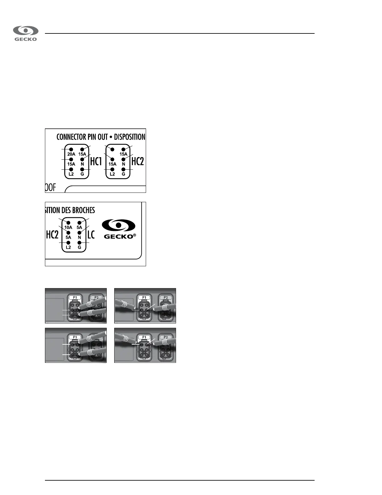
HC1
Pin 1 (Line 2)
Pin 2 (Output (1) high speed, 15A)
Pin 3 (Output (1) high speed, 20A)
Pin 4 (Ground)
Pin 5 (Neutral)
Pin 6 (Output (1) low speed, 15A)
Measuring tension on in.xe:
Example: your pump 1 high speed (240V) is not working.
Refering to the front connector identifiers, you may see the pump 1 output is on the P1 connector�
You may then refer to the “Connector pin out" on the front of the in�xe, you will notice the output for your pump 1 is on
pins 2 and 3 (pump 1 high speed 20A and 15A) and the return should be on pin 1 (line 2) for a 240V pump and on pin
5 (neutral) for a 120V pump�
Measure the tension between P1 connector pins 2-3 (output pump 1 high speed 20A
and 15A) and pin 1 or 5 (return line 2 or neutral), you should measure:
120 V for a 120 V pump or accessory
240 V for a 240 V pump or accessory
LC (1)
Pin 1 (Line 2)
Pin 2 (Output (3), 5A)
Pin 3 (Output (3-4), 10A)
Pin 4 (Ground)
Pin 5 (Neutral)
Pin 6 (Output (4), 5A)
LC (2)
Pin 1 (Line 2)
Pin 2 (Output (4), 5A)
Pin 3 (Output (4), 10A)
Pin 4 (Ground)
Pin 5 (Neutral)
Pin 6 (NC)
HC2
Pin 1 (Line 2)
Pin 2 (Output (2) high speed, 15A)
Pin 3 (NC)
Pin 4 (Ground)
Pin 5 (Neutral)
Pin 6 (Output (3) low speed, 15A)
P1
P1
P2P2
P5
P5
P3 P3
Troubleshooting
3
3
2 5
5 2
6
6
4
4
3
1
6
2
5
1
1
4
 Loading...