App4-2
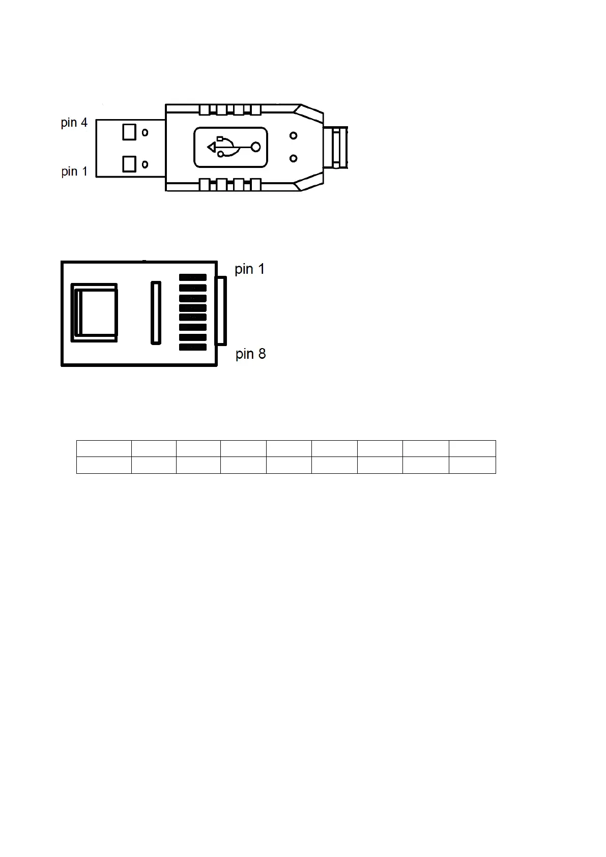
2. USB Interface Cable Pin Definition
2.1 RS232/USB at PC side.
RS485/RJ45 connector at inverter side.
2.2 RS485/RJ45 Pin Definition.
Note:
1. A/B phase signal (Pin1&Pin2) is differential mode data signal of RS485.
2. VCC&GND is the +5Vdc power supply provided by inverter internal power source.
3. Notice
3-1. Please turn off the power before you connect the cable..
3-2. Once inverter is powered off during communication. PC software will show “communication error”.
3-3. If there is any error during communication, please check the wiring connection and restart the pc
software.

 Loading...


