4-13
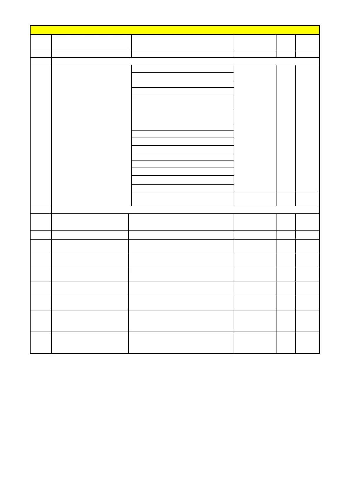
Group 03- Multi function Digital Inputs/Outputs
No. Description Range
Factory
Unit Note
03-11
Output Relay(RY1)
1 -
2:Setting Frequency Reached
3:Frequency Reached (3-13±3-14)
4:Output Frequency Detection1(>
3-13)
5:Output Frequency Detection2(<
3-13)
7:Momentary AC Power Loss
10:Motor Overload Protection(OL1)
11:Drive Overload Protection(OL2)
13:Output Current Reached
15:PID feedback disconnection
detection
03-13
Output frequency detection
0.00~599.00 0.00 Hz *1
03-15
Output Current Detection
Level
0.1~999.9 0.1 A
03-16
Output Current Detection
Period
0.1~10.0 0.1 s
03-17
External Brake Release
level
0.00~20.00 0.00 Hz
03-18
External Brake Engage
Level
0.00~20.00 0.00 Hz
03-19
Relay Output function type
0:A (Normally open)
1:B (Normally close)
0 -
03-20
Braking Transistor On
Level
200V: 240.0~400.0V
400V: 500.0~800.0V
380/400V:690
VDC
03-21
Brake Transistor Off Level
200V: 240.0~400.0V
400V: 500.0~800.0V
380/400V:650
VDC
※ “NO” indicates normally open, “NC” indicates normally closed.

 Loading...


