3580415F_MSW_GFX4-IR_05-2019_ENG
FUNCTIONAL DIAGRAM
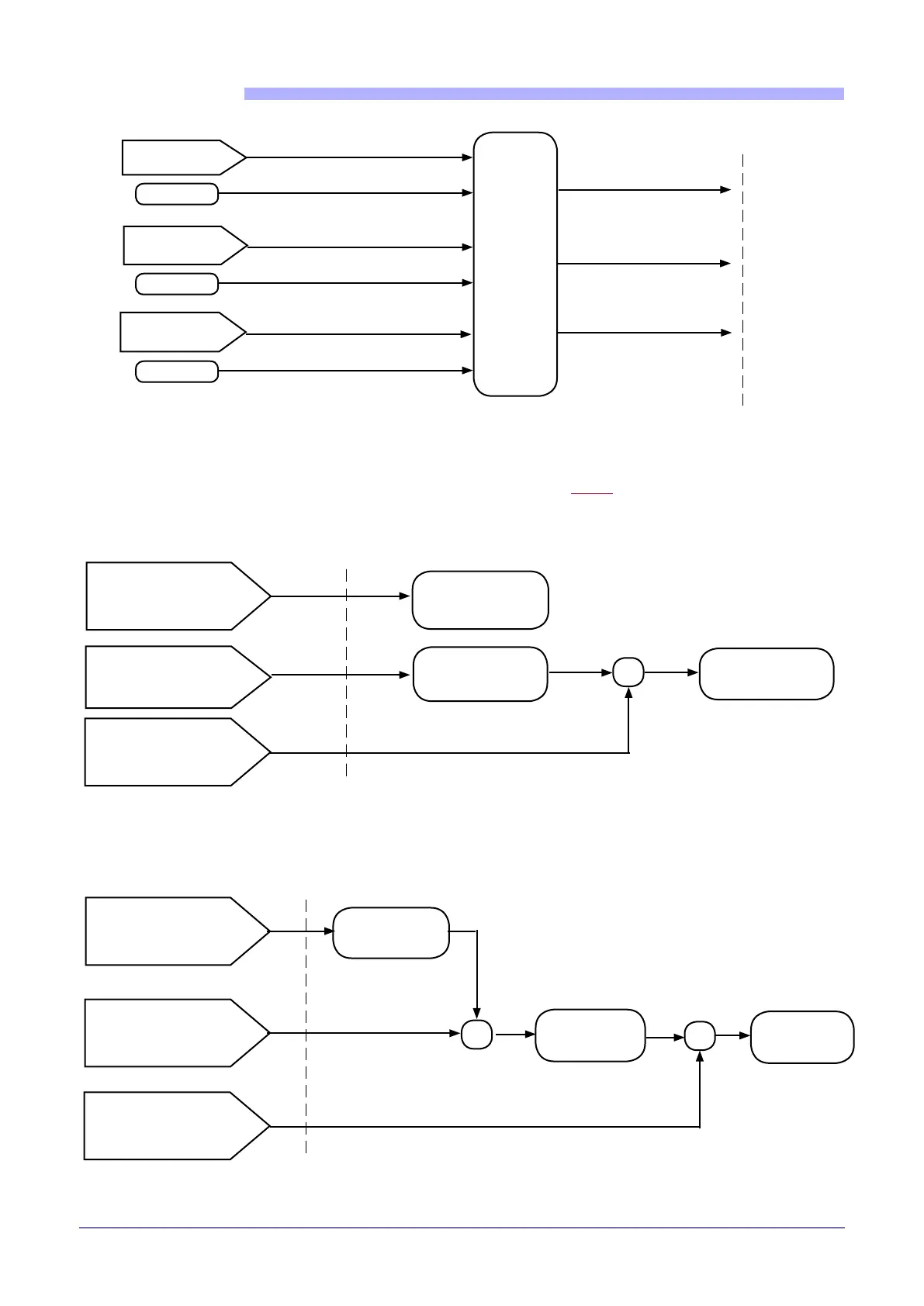
Alarm setpoint
Hb.tr zone 1
State of alarm HB phase 1
I.1on
Function of
HB alarm
and time for
activation
of HB alarm
(Hb.F, Hb.t)
See outputs
State of alarm HB phase 2 (*)
Alarm setpoint
Hb.tr zone 2 (*)
Alarm setpoint
Hb.tr zone 3 (*)
(*) - Only for 3-phase applications
I.2on
I.3on
State of alarm HB phase 3 (*)
HB Alarm
HB Calibration in mode PA
NOTE:
the value of setpoint Hb.tr for the HB alarm is calculated in two different ways, depending on the selected function
mode:
if ZC, BF, HSC mode: ................................................... Hb.tr = A.Hb
if PA mode .................................................................... Hb.tr = A.Hb *
V(Ou.P)
HB Calibration in modes ZC - BF - HSC
Percent HB alarm
setpoint of current
read in HB calibration
Hb.P
HB alarm
setpoint
A.Hb
- Calibration ON bit 112
- Function dIG / dIG.2
Value of Ou.P
control outputs
Value of CT input
with output on (phase 1)
I.1ON
CT read in
HB calibration
Hb.TA
Ou.P power in
Hb.Pw
calibration
X
Ou.P power
in Hb.Pw
calibration
CT read in
HB calibration
Hb.TA
HB alarm
setpoint
A.Hb
- Calibration ON bit 112
- Function dIG / dIG.2
(Load current referred to
100% of conduction)
X
X
Percent HB alarm
setpoint of current
read in HB calibration
Hb.P
Value of Ou.P
control outputs
Value of CT input
with output on (phase 1)
I.1ON

 Loading...


