40
80415F_MSW_GFX4-IR_05-2019_ENG
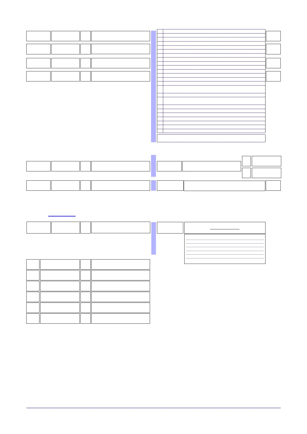
166
rL.3
R/W
Allocation of reference signal
170
rL.4
R/W
Allocation of reference signal
171
rL.5
R/W
Allocation of reference signal
172
rL.6
R/W
Allocation of reference signal
2
35
4
160
308
319
R
State of outputs rL.x MASKOUT
bit
0 State rL.1
1 State rL.2
2 State rL.3
3 State rL.4
4 State rL.5
5 State rL.6
Table of output states
0 ... 63
12
bit
STATE rL.1
OFF = Output off
ON = Output on
R
13
bit
STATE rL.2
OFF = Output off
ON = Output on
R
14
bit
STATE rL.3
OFF = Output off
ON = Output on
R
15
bit
STATE rL.4
OFF = Output off
ON = Output on
R
16
bit
STATE rL.5
OFF = Output off
ON = Output on
R
17
bit
STATE rL.6
OFF = Output off
ON = Output on
R
Read state
152
9
(t.1
R/W
OUT 1 (HEAT) cycle time
1 ...200 sec
(0.1 ...20.0 sec)
DIP5 = OFF
(resistive load)
Set 0 for GTT function
See POWER CONTROL
159
(t.2
R/W
OUT 2 (COOL) cycle time
1 ...200 sec
(0.1 ...20.0 sec)
20
0
4
DIP5 = ON
(inductive load)
2 AL1 - alarm 1
3 AL2 - alarm 2
4 AL3 - alarm 3
5 AL.HB or POWER_FAULT with HB alarm (TA1 OR TA2 OR TA3)
6 LBA - LBA alarm
7 IN1 - repetition of logic input DIG1
8 AL4 - alarm 4
9 AL1 or AL2
10 AL1 or AL2 or AL3
11 AL1or AL2 or AL3 or AL4
12 AL1 and AL2
13 AL1 and AL2 and AL3
14 AL1 and AL2 and AL3 and AL4
15 AL1 or AL.HB or POWER_FAULT with HB alarm (TA1 OR TA2 OR TA3)
16 AL1 or AL2 or (AL.HB or POWER_FAULT) with HB alarm (TA1 OR TA2
OR TA3)
17 AL1 and (AL.HB or POWER_FAULT) with HB alarm (TA1 OR TA2 OR TA3)
18 AL1 and AL2 and (AL.HB or POWER_FAULT) with HB alarm (TA1 OR TA2
OR TA3)
19 AL.HB - HB alarm (TA2)
20 AL.HB - HB alarm (TA3)
21 Setpoint power alarm
22 AL.HB - HB alarm (TA1)
23 POWER_FAULT
24 IN2 - repetition of logic input DIG2
29 Communication error
+ 32 for denied logic level at output
+ 128 to force output to zero

 Loading...


