L
NAPCO Security Systems
X
GEM-P9600 Installation Instructions
WI742E 2/04
!
Page 47
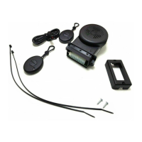
1. Program the selected zone(s) (1–6) for 2-Wire Smoke Detec-
tors and Fire.
2. Cut out the 2700Ω resistor (color code: red/violet/red) associ-
ated with the selected zone(s). See table below.
3. Install a 130Ω resistor across the 2 terminals of each zone
used (color code: brown/orange/brown).
4. Wire positive (+) terminal of smoke detector to terminal 28.
Wire negative (-) terminal of smoke detector to positive (+)
terminal of the zone.
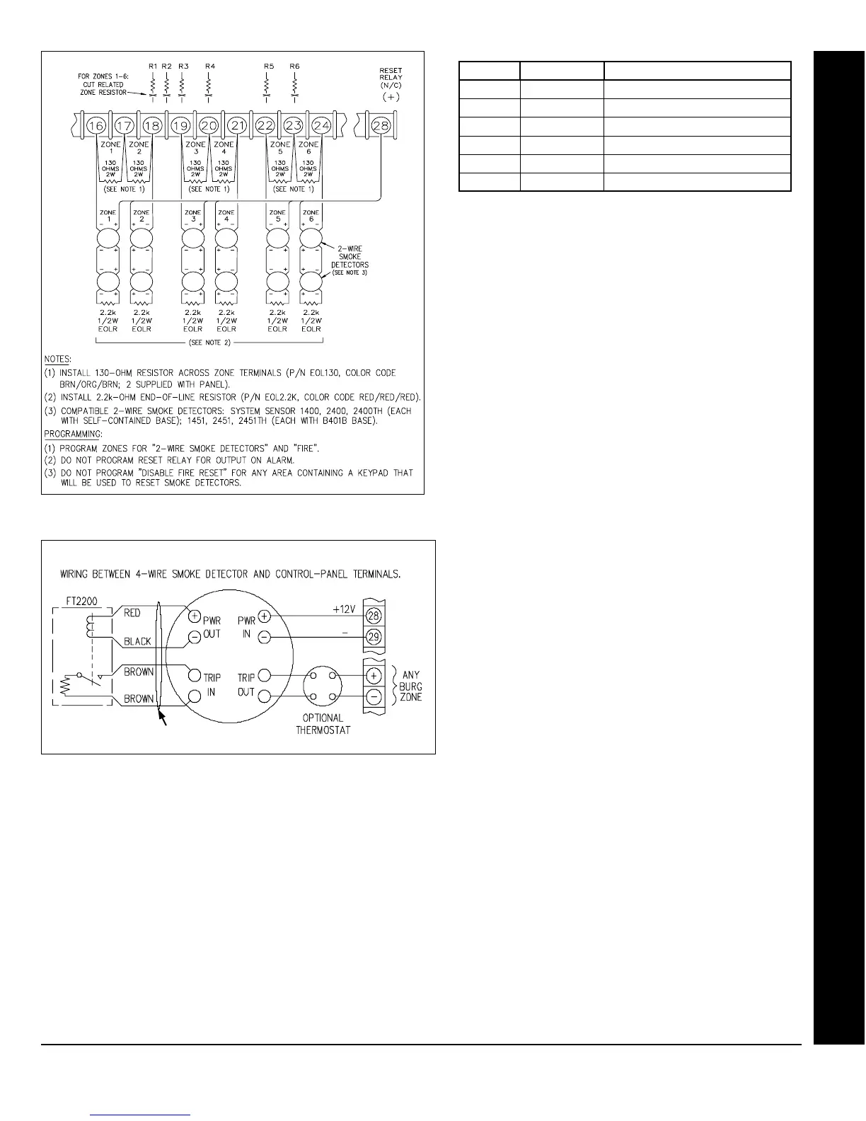
Four-Wire Smoke Detectors.
If installing 4-wire
smokes, subtract smoke-detector alarm current from
available standby current. See COMPATIBLE UL-
LISTED DEVICES.
Wire 4-wire smokes as shown in the following wiring dia-
gram. Program each zone for Fire. Also program zones
for Pulse Burglary Output, and Disable Fire Reset in the
applicable area(s) (System Options). If they are of the
self-resetting type, 4-wire smokes may be powered from
Terminals 13 and 14 (AUX. PWR.) instead of Terminal 28
and 29, thus freeing the Reset Relay for other uses.
Split Reporting See Report Telco 3
Start Exit Delay After Ringback
When a closing report is successfully received, the central station will acknowledge by returning a kissoff signal. When the kis-
soff is received by the communicator, a 2-second ringback tone will sound at the keypad. Start Exit Delay After Ringback will cause
the exit delay to start after the ringback sounds.
If this option is chosen and no ringback sounds shortly after the control panel is armed, exit delay will not start and opening the
exit/entry door will cause an instant alarm. To manually start the exit delay, select the START EXIT TIME function, then press the
J
or
U
button to execute.
Note:
(1) If this feature is selected, Exit/Entry Follower Zones will not arm until either a ringback sounds or the START EXIT
TIME function is used. (2) If communicator, telephone lines or central-station receiver is out of service, the system will be armed with-
out communication capability.
Status Report See Closing Report
Wiring diagram, 4-wire smoke detectors
Additional 4-wire smokes
ZONE RESISTOR LOCATION ON BOARD
1 R1 ABOVE TERMINAL 18
2 R2 ABOVE TERMINAL 18/19
3 R3 ABOVE TERMINAL 19
4 R4 ABOVE TERMINAL 20
5 R5 ABOVE TERMINAL 22
6 R6 ABOVE TERMINAL 23
Connecting 2-wire smoke detectors to zones 1-6
GLOSSARY
 Loading...