514
21/28
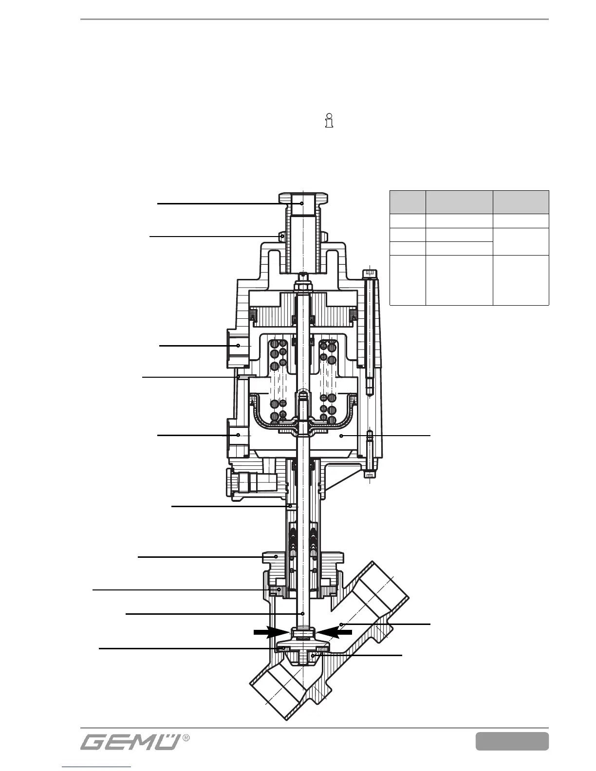
IMPORTANT
Replace gasket (4) during every
actuator disassembly / assembly.
A
4
14
1
Disc
Connection R
Vent hole
Connection V
Relief bore hole
Stroke limiter
Locking nut
Union nut
Spindle
Apply pliers here
Item Name of the
spare part
Order
description
1 Valve body K 500...
4 Gasket
514...SVS...
14 Shut-off seal
A Actuator 9514 K...
(see order
data , section
“Actuator
size“)
}
connections and screw it down hand
tight using union nut (a).
6. Tightening the union nut (a) with an open-
end wrench rotates the actuator clock-
wise approx. 90° to the required position.
7. Check tightness of completely
assembled valve.
10.3 Actuator and gasket
assembly
1. Move actuator (A) to the open position.
2. Clean all parts.
3. Place new gasket (4) in valve body (1).
4. Actuator rotatable 360°. Position of the
control air connections are optional.
5. Place actuator (A) on valve body (1)
approx. 90° anticlockwise to the
required end position of the control air
11 Sectional drawing and spare parts