Manual Part NO.: 119509-00 Rev. A
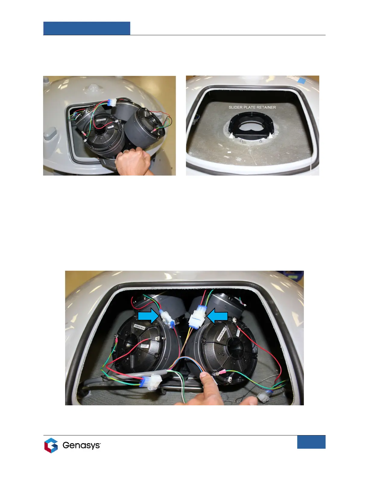
4. Insert the assembly into the emitter by lowering the assembly into the opening (Figure 9).
• Rest the bottom of the assembly on the slider plate retainer found inside the emitter
and start to slide the manifold towards the back of the emitter (Figure 10).
5. Prior to sliding the assembly completely into the emitter, connect the cables from DR1 and
DR2 (the two drivers at the rear of the assembly) to the emitter connection cables (Figure
11).
• Align the mating faces of the connectors and firmly push them together until you
hear a click. Press the locking latches on the sides of the connectors to confirm that
they are fully engaged with the locking tabs.
• These driver cables can connect to any of the emitter connection cables.