Manual Part NO.: 119509-00 Rev. A
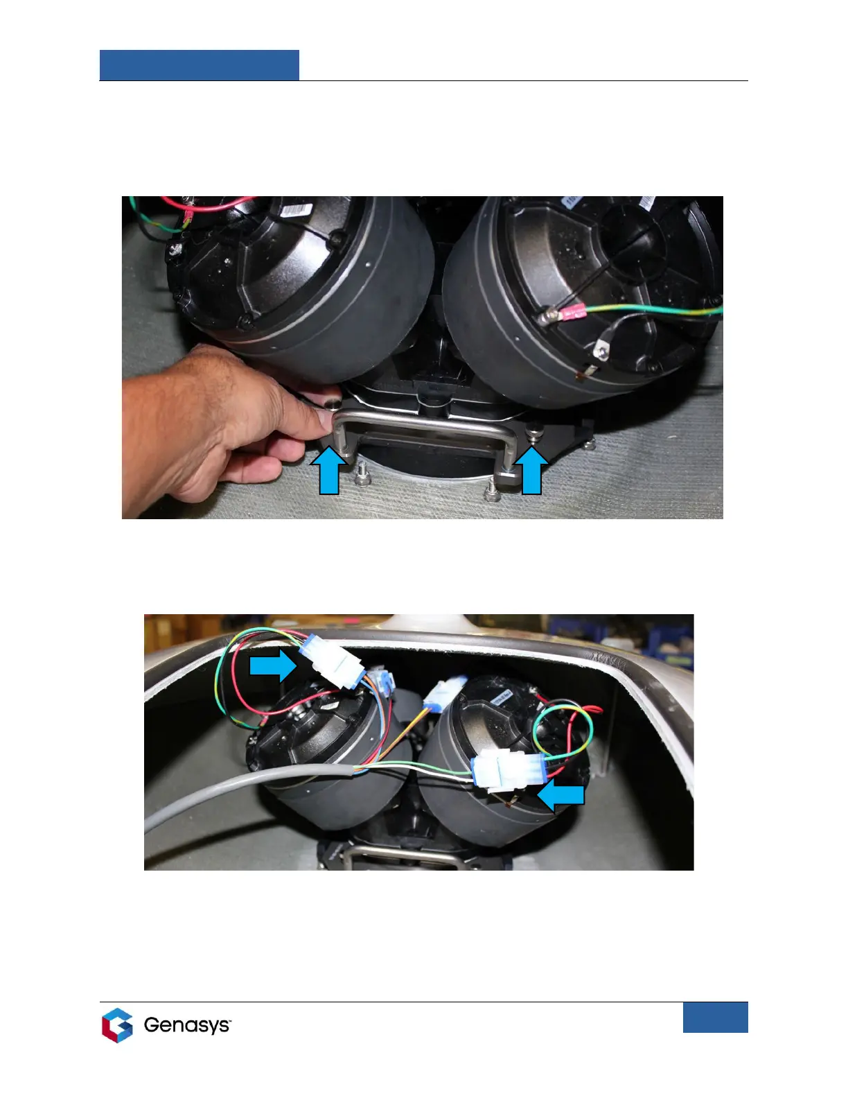
6. Slide the assembly completely into the slider plate retainer so the mounting holes align.
7. Hand-tighten the two provided thumbscrews to lock the assembly into position (Figure
12).
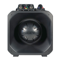
8. Connect the cables from DR3 and DR4 (the two front drivers) to the remaining emitter
connection cables (Figure 13).
9. Replace the access panel on the emitter and fully tighten the panel’s bolts.
• Turn the bolts by hand to secure the internal clamps and then tighten the panel’s
bolts using a 7/16-inch wrench.
COMPLETELY ALIGNED