Generac
®
Power Systems, Inc. 3
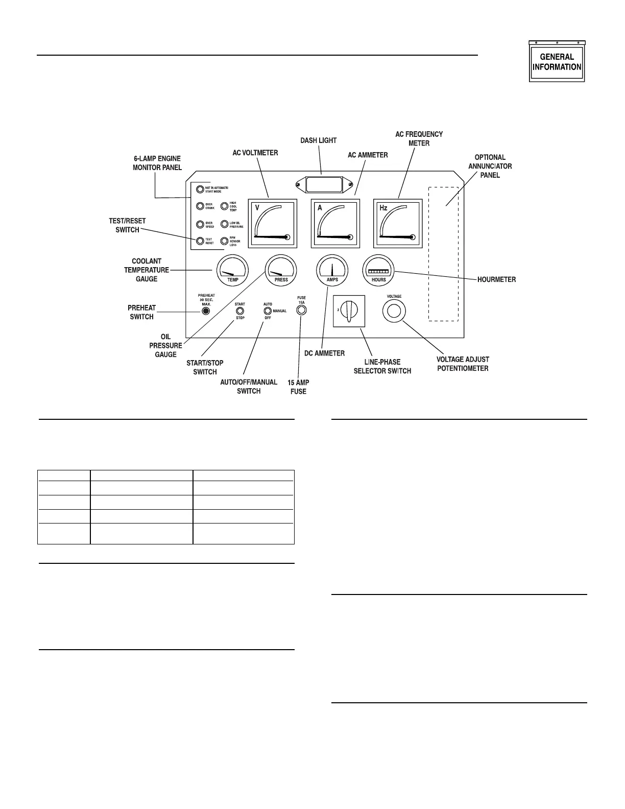
1.4.4 LINE-PHASE SELECTOR SWITCH
This four-position switch permits selection of either
line-to-line or line-to-neutral readings on the panel
voltmeter and ammeter. Switch positions are as fol-
lows:
1.4.5 VOLTAGE ADJUST POTENTIOMETER
This potentiometer permits the operator to “fine-
adjust” the generator’s AC output voltage. Adjustment
range is plus or minus five percent from the mid-
point. Turn the knob clockwise to increase voltage,
counterclockwise to decrease voltage.
1.4.6 COOLANT TEMPERATURE GAUGE
This gauge indicates the engine coolant temperature.
Normal operating temperature should read between
185° to 215°F (85° to 102°C). If coolant temperature
exceeds a safe level, the engine shuts down automat-
ically.
NOTE:
Actual coolant temperature reading may vary due
to variables, such as, ambient temperature,
applied load, or cooling system condition.
1.4.7 OIL PRESSURE GAUGE
This gauge indicates oil pressure during operation.
After warm-up, oil pressure should be about 25-90
psi. Generac recommends that the operator record
the normal oil pressure during initial startup.
Sudden changes in oil pressure after first starting
indicate a possible engine problem.
NOTE:
Engine oil pressure may vary, depending on oil
viscosity, oil temperature, engine speed, ambient
temperature, etc. The engine automatically shuts
down if oil pressure drops below a safe level.
(10 psi.)
1.4.8 DC AMMETER
The engine is equipped with a belt-driven DC alter-
nator, which charges the battery while the unit is run-
ning. This ammeter indicates the rate of charge to the
battery during operation. If the needle drops to the
left of zero, the battery is discharging. Investigate and
correct this problem immediately. Erratic movement
of the needle should also be corrected immediately.
1.4.9 HOURMETER
The hourmeter provides a continuous indication of
engine/generator operating time, in hours and tenths
of hours. Use the hourmeter with the periodic main-
tenance schedule.
◆
◆
◆
Section 1 — General Information
“C” Option Control Panel