6 Generac
®
Power Systems, Inc.
1.7 OPTIONAL REMOTE
ANNUNCIATOR
An optional 18-light REMOTE annunciator panel that
can be mounted on a wall (Figure 1.3) is also avail-
able. For information on the remote annunciator pan-
els, ask the local dealer/distributor or consult the fac-
tory. Ask for information on the Models 9555 and
9556 remote annunciator panels. The following apply
to the remote annunciator panels:
• It is designed for use with installation having a
Generac Power Systems GTS-type transfer switch
and a “C” Option control panel.
• The panel is available in both flush-mounted
(Model 9556) and surface-mounted (Model 9555)
configurations.
• The panel has a built-in audible alarm horn, with a
reset switch to turn off the horn without disturbing
the lighted indication.
• Remote monitoring of the standby generator set
provides enough information to avoid unnecessary
maintenance trips to the generator site.
Figure 1.3 — Optional 18-Light Remote
Annunciator
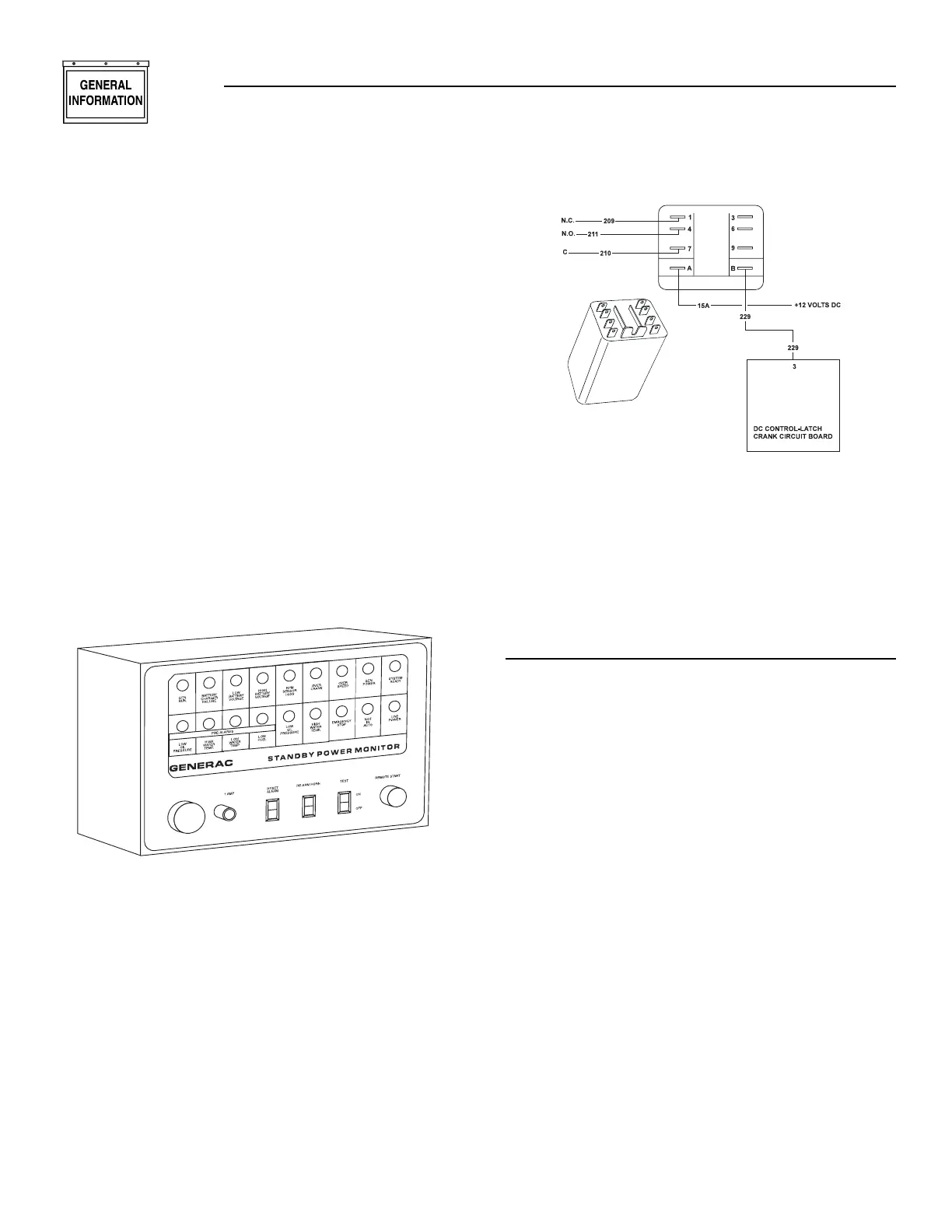
1.8 STANDARD ALARM RELAY
The generator’s DC control/latch-crank circuit board
is equipped with an alarm relay “driver”. All units
with “C” Option control panels are equipped with an
alarm relay that is connected to the circuit board
driver (Figure 1.4). If any one or more of the five
annunciated shutdown faults occur, the circuit board
driver energizes the optional alarm relay.
A remote-mounted alarm or annunciator device may
be connected across the relay contacts so that a fail-
ure will turn on the remote alarm or device. The con-
nected alarm device may range from an alarm horn
to a warning light to a telephone dialer with a pre-
recorded message. The alarm relay normally-open,
normally-closed, and common contacts are shown in
Figure 1.4.
Figure 1.4 — Standard Alarm Relay
1.9 PREPARATION BEFORE STARTUP
The instructions in this section assume that the
standby generator has been properly installed, serv-
iced, tested, adjusted, and otherwise prepared for
use by a competent, qualified installation contractor.
Be sure to read RULES FOR SAFE OPERATION on
the inside of the front cover carefully, before attempt-
ing to operate this (and related) equipment.
1.9.1 PRIOR TO INITIAL STARTUP
Before starting the generator for the first time, the
installer must complete the following:
• Properly locate and properly mount the generator,
transfer switch, and other standby system compo-
nents, in strict compliance with applicable codes,
standards, and regulations.
• Make sure the fuel supply system to the generator
(a) delivers the correct fuel at the correct pressure,
and (b) is properly purged and leak-tested accord-
ing to code. No fuel leakage is permitted.
• Have the engine crankcase properly filled to the
correct level with the recommended oil.
• Have engine cooling system properly filled with rec-
ommended coolant mixture. Check the system for
leaks and other problems.
• If engine is equipped with a mechanical governor,
make sure the governor is properly filled with oil.
Use crankcase oil to fill.
• Check engine v-belt tension and belt condition.
• Make sure the generator is properly connected to
an approved earth ground.
• The generator battery must be fully charged, prop-
erly installed and interconnected, and ready for
use.
◆
Section 1 — General Information
“C” Option Control Panel