Section 1
GENERATOR FUNDAMENTALS
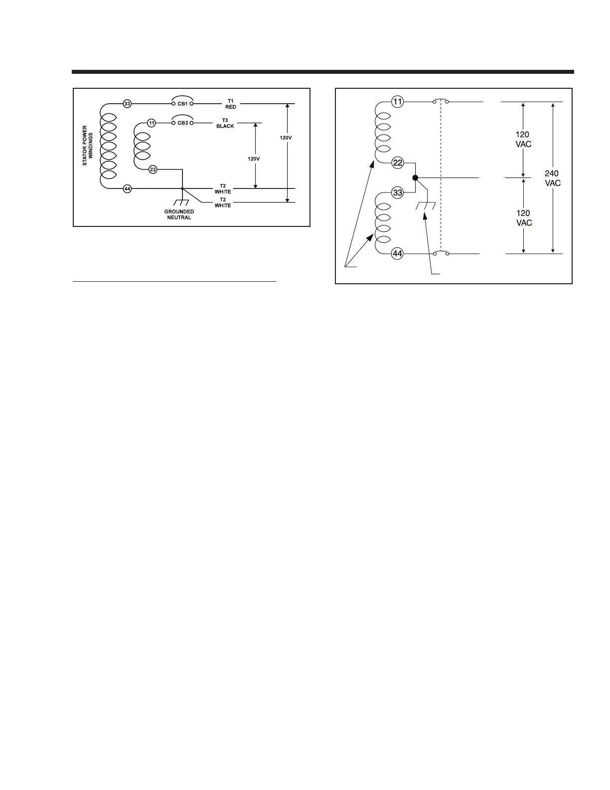
Figure 1-8. – Connection for 120 Volts Only
RECONNECTION FOR DUAL VOLTAGE OUTPUT:
When connected for dual voltage output, Stator output
leads 11 and 44 form two “hot” leads (T1 – Red, and
T3 – Black). The junction of leads 22 and 33 form the
“Neutral” line (T2 – White).
For dual voltage output, the “Neutral” line remains
grounded.
NOTE: For units with two 20 amp or two 30 amp
main breakers, the existing breakers may be re-
used when reconnecting for dual voltage output.
However, on units with a 30 amp and a 20 amp
main breaker, you may wish to install a 2-pole
breaker that is rated closer to the unit’s rated
capacity (use two 25 amp main breakers).
T1
RED
T2
WHITE
T3
BLACK
GROUNDED NEUTRAL
STATOR WINDINGS
CB1
CB2
Figure 1-9 - Connection for 120/240 Volts
NOTE: If this generator has been reconnected
for dual voltage AC output (120/240 volts), the
replacement line breakers should consist of
two separate breakers with a connecting piece
between the breaker handles (so that both break-
ers operate at the same time). If the unit is recon-
nected for dual voltage, it is no longer RVIA listed.
Page 7
 Loading...