EasyManua.ls Logo

Generac Power Systems MEGAFORCE 6500

Generac Power Systems MEGAFORCE 6500
36 pages
To Next Page IconTo Next Page
Loading...
Model No. 1021-0 (6500 Watt AC Generator) Manual No. B1479 Revision 3 (3/14/2000)
Modèle No 1021-0 (Générateur c.a. de 6500 watts) Manuel No B1479 Révision 3 (14 Mars 2000)
Visit our Generac website: www.generac-portables.com
Visiter notre Generac website: www.generac-portables.com
Problems?
Questions?
Before taking your
unit back to the store,
call the generator
helpline at
18002701408
MF 85 CT
MEGAFORCE 6500
GENERAC
The Reliable Ones
Safety
Assembly
Operation
Maintenance
Parts
French
Sûreté
Assemblée
Opération
Entretien
Parties
Français
Les problèmes?
Les questions?
Avant de prendre votre
dos d'unité au magasin,
appeler le helpline de
générateur à
18002701408
MF 85 CT
Extended Life Generator Owner’s Manual
Manuel de l’Utilisateur pour le Générateur à Durée de vie Prolongée
Question and Answer IconNeed help?

Do you have a question about the Generac Power Systems MEGAFORCE 6500 and is the answer not in the manual?

Generac Power Systems MEGAFORCE 6500 Specifications

General IconGeneral
Max Watts6500
Engine Displacement389cc
Fuel TypeGasoline
EngineGenerac OHV Engine
Outlet Types2 x 120V 20A (5-20R), 1 x 120/240V 30A (L14-30R)

Summary

Equipment Description and Safety Rules

General Safety Warnings

Consolidates all critical DANGER and WARNING statements regarding safe generator use.

Safety Rules Continued

Electrical, Gasoline, and Operational Safety

Covers electrical shock, gasoline handling, cooling air, and load connection safety.

Grounding the Generator

Explains the necessity and procedure for proper generator grounding.

Know Your Generator

Generator Components and Controls Overview

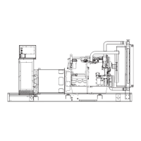
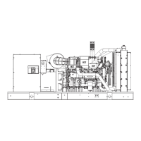
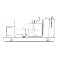
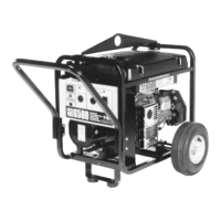
Provides an overview of generator components and descriptions of key controls.

Assembly Instructions

Unpacking and Initial Setup

Details safe unpacking procedures and initial setup for the generator.

Assembly and Pre-Start Procedures

Wheel and Lift Kit Installation

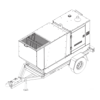
Step-by-step guide for installing the wheel and lift kit components.

Fluid Preparation

Instructions for properly adding engine oil and gasoline before operation.

Generator Operation

Starting the Engine Procedure

Step-by-step guide for starting the generator engine, including choke and switch usage.

Generator Operation Continued

Connecting Loads and Stopping Engine

Procedures for connecting electrical loads and safely stopping the engine.

Idle Control and Battery Charging

Details automatic idle control for fuel economy and battery charging procedures.

Generator Operation Further

Battery Connections

Illustrates and describes connecting battery charge cables to terminals.

Cold Weather Operation and Shelter

Guidance for cold weather operation and using the original box as a shelter.

Control Panel and Receptacles

GFCI Receptacle and Testing

Explains the GFCI receptacle, its protection, and the monthly testing procedure.

120240 Volt AC Locking Receptacle

Details the 120/240V locking receptacle, its ratings, and cord set requirements.

Control Panel and Receptacles Continued

120 Volt AC Locking Receptacle

Provides information on the 120V locking receptacle and compatible cord sets.

12 Volt DC Receptacle

Describes the 12V DC receptacle for battery charging and its limitations.

Dont Overload the Generator

Wattage Reference Guide

Offers a reference list of common devices and their typical wattage requirements.

General Maintenance and Storage

Maintenance Procedures

Details engine and generator maintenance, including cleaning instructions.

Storage Guidelines

Provides guidelines for proper generator storage, including fuel and environment.

Specifications

Troubleshooting Guide

No AC Output

Troubleshooting steps for when the engine runs but no AC output is available.

Engine Performance Issues

Diagnoses and resolves issues like engine bogging, rough running, shutdown, or power loss.

Schematic Diagram

Key Circuit Boards

Identifies the Power Regulator and System Control boards in the schematic.

Wiring Diagram

Stator and Engine Control Wiring

Shows wiring for the stator and engine control circuits.

Exploded View - Main Unit

Main Unit Component Identification

Lists numbered parts of the main assembly for component identification.

Parts List - Main Unit

Major Assemblies and Frame Parts

Lists parts for major assemblies, frame, housing, engine, and electrical components.

Fasteners, Hardware, and Minor Components

Details fasteners, hardware, exhaust, air intake, and control panel related parts.

Exploded View and Parts List - Control Panel

Control Panel Assembly Parts

Lists all components and parts related to the control panel assembly.

Exploded View and Parts List - Wheel Kit

Wheel Kit Components and Hardware

Lists all components and hardware for the wheel kit, including handle, wheels, and axle.

Limited Warranty Information

Warranty Terms and Conditions

Covers warranty periods, usage types, exclusions, and legal disclaimers.

Related product manuals