GENERATOR
RESTRAINT
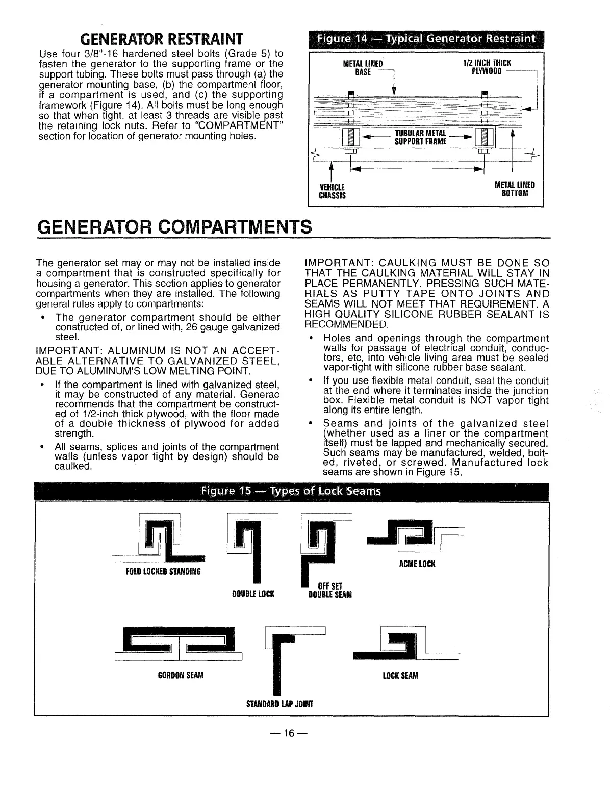
Use four 3/8"-i 6 hardened steel bolts (Grade
5}
to
fasten the generator to the supporting frame or the
support tubing. These
bolts must pass through
(a)
the
generator mounting base,
(b)
the compartment floor,
if a compartment is used, and (c) the supporting
framework (Figure 14).
All bolts must
be
long enough
so
that when tight, at least 3 threads are visible past
the retaining
lock nuts. Refer to "COMPARTMENT"
section for location of generator mounting holes.
Figure
14-
Typical
Generator
Restraint
VEHICLE
CHASSIS
METAL
LINED
BOTTOM
GENERATOR COMPARTMENTS
The generator set may or may not
be
installed inside
a compartment that is constructed specifically for
housing a generator. This section
applies to generator
compartments when they are
installed. The following
general rules apply
to compartments:
• The generator compartment should be either
constructed of, or
lined with, 26 gauge galvanized
steel.
IMPORTANT: ALUMINUM
IS
NOT
AN
ACCEPT-
ABLE
ALTERNATIVE
TO
GALVANIZED
STEEL,
DUE
TO
ALUMINUM'S LOW MELTING POINT.
•
If
the compartment
is
lined with galvanized steel,
it
may
be
constructed of any material. Generac
recommends that the compartment
be
construct-
ed
of
1/2-inch thick plywood, with the floor made
of a
double
thickness
of
plywood
for
added
strength.
•
All
seams, splices and joints
of
the compartment
walls (unless vapor tight by design) should
be
caulked.
IMPORTANT:
CAULKING
MUST
BE
DONE
SO
THAT THE CAULKING MATERIAL WILL STAY IN
PLACE PERMANENTLY. PRESSING SUCH MATE-
RIALS
AS
PUTTY
TAPE
ONTO
JOINTS
AND
SEAMS WILL NOT MEET THAT REQUIREMENT. A
HIGH QUALITY SILICONE RUBBER SEALANT
IS
RECOMMENDED.
• Holes and openings through the compartment
walls for passage of electrical conduit, conduc-
tors,
etc,
mto
vehicle living area must
be
sealed
vapor-tight with silicone rubber base sealant.
•
If
you
use flexible metal conduit, seal the conduit
at the end where it terminates inside the junction
box.
Flexible metal conduit is NOT vapor tight
along its entire length.
•
Seams
and
joints
of
the
galvanized
steel
(whether used as a liner or the
compartment
itself) must
be
lapped and mechanically secured.
Such seams may
be
manufactured, welded, bolt-
ed,
riveted,
or
screwed.
Manufactured
lock
seams are shown
in
Figure 15.
Figure
19-
Types
of
Lock Seams
--
---~----~~
---
___f._-
---~
- -
-~---~
- -
--~~-~-----~-
---~~~------
FOLD
LOCKED
STANDING
GORDON
SEAM
DOUBLE
LOCK
OFF
SET
DOUBLE
SEAM
STANDARD
LAP
JOINT
-16-
ACME
LOCK
LOCK
SEAM
 Loading...