GENERATOR
CONTROL
PANEL
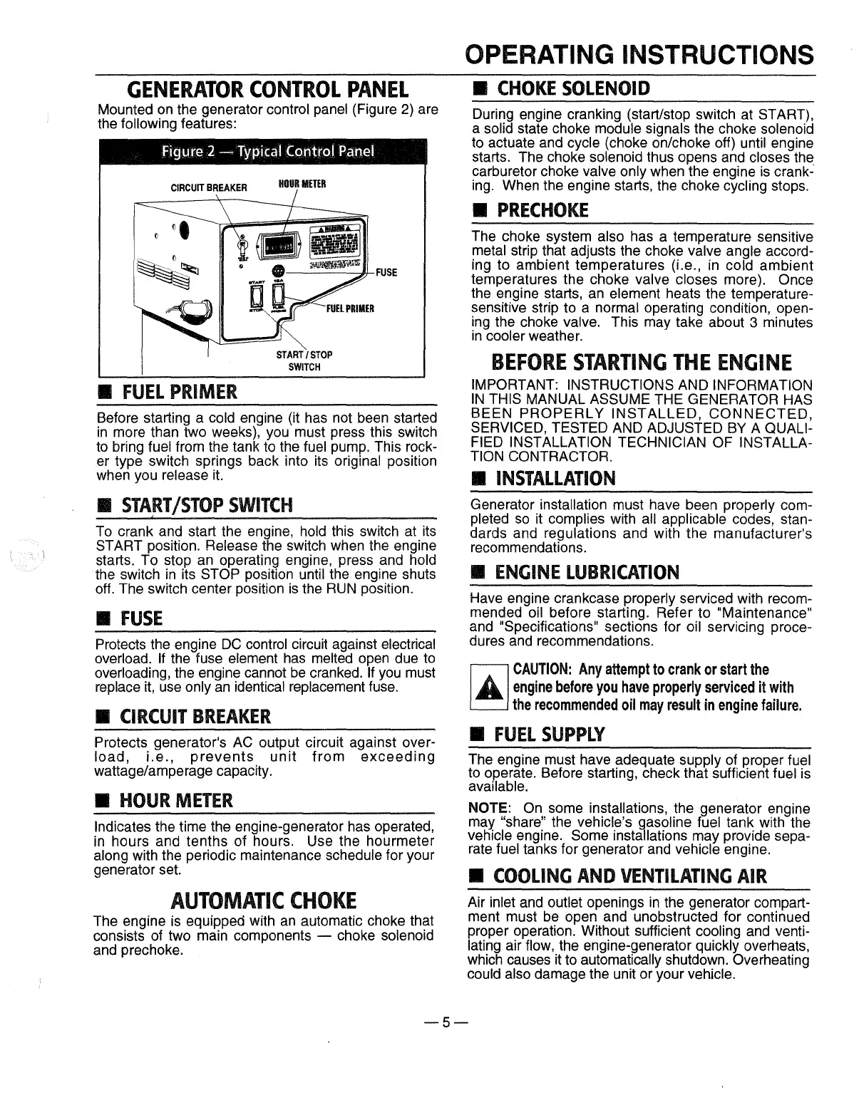
Mounted
on
the generator control panel (Figure
2)
are
the
following features:
Figure
2-
Typical Control Panel
•
FUEL
PRIMER
Before starting a cold engine (it has not been started
in
more than two weeks), you must press this switch
to
bring fuel from the tank to the fuel pump. This rock-
er type switch springs back into its original position
when you release
it.
•
START
/STOP
SWITCH
To crank and start the engine, hold this switch at its
START position. Release the switch when the engine
starts.
To stop
an
operating engine, press and hold
the switch
in
its STOP position until the engine shuts
off.
The switch center position
is
the
RUN
position.
•
FUSE
Protects the engine
DC
control circuit against electrical
overload.
If the fuse element
has
melted open due to
overloading, the engine cannot
be
cranked. If you must
replace
it,
use only
an
identical replacement fuse.
•
CIRCUIT
BREAKER
Protects generator's
AC
output circuit against over-
load,
i.e.,
prevents
unit
from
exceeding
wattage/amperage capacity.
•
HOUR
METER
Indicates the time the engine-generator has operated,
in
hours and tenths of hours. Use the hourmeter
along with the periodic maintenance schedule for your
generator set.
AUTOMATIC
CHOKE
The engine
is
equipped with
an
automatic choke that
consists of two main components
- choke solenoid
and prechoke.
OPERATING INSTRUCTIONS
•
CHOKE
SOLENOID
During engine cranking (start/stop switch at START),
a solid state choke module signals the choke solenoid
to actuate and cycle (choke on/choke off) until engine
starts.
The choke solenoid thus opens and closes the
carburetor choke valve only when the engine
is
crank-
ing. When the engine starts, the choke cycling stops.
•
PRECHOKE
The choke system also has a temperature sensitive
metal strip that adjusts the choke valve angle accord-
ing to ambient temperatures (i.e., in cold ambient
temperatures the choke valve closes more).
Once
the engine starts,
an
element heats the temperature-
sensitive strip to a normal operating condition, open-
ing the choke valve. This may take about 3 minutes
in
cooler weather.
BEFORE
STARTING
THE
ENGINE
IMPORTANT: INSTRUCTIONS AND INFORMATION
IN
THIS MANUAL ASSUME THE GENERATOR HAS
BEEN
PROPERLY
INSTALLED,
CONNECTED,
SERVICED, TESTED AND ADJUSTED
BY
A QUALI-
FIED INSTALLATION TECHNICIAN OF INSTALLA-
TION CONTRACTOR.
•
INSTAllATION
Generator installation must have been properly com-
pleted
so
it complies with all applicable codes, stan-
dards and regulations and with the manufacturer's
recommendations.
•
ENGINE
LUBRICATION
Have engine crankcase properly serviced with recom-
mended
oil before starting. Refer to "Maintenance"
and "Specifications" sections for oil servicing proce-
dures and recommendations.
CAUTION:
Any
attempt
to
crank
or
start
the
engine
before
you
have
properly
serviced
it
with
the
recommended
oil
may
result
in
engine
failure
.
•
FUEL
SUPPLY
The engine must have adequate supply of proper fuel
to operate. Before starting, check that sufficient fuel is
available .
NOTE: On some installations, the generator engine
may
"share" the vehicle's gasoline fuel tank with the
vehicle engine.
Some installations may provide sepa-
rate fuel tanks for generator and vehicle engine.
•
COOLING
AND
VENTILATING
AIR
Air inlet and outlet openings
in
the generator compart-
ment must be open and unobstructed for continued
proper operation. Without sufficient cooling and venti-
lating air flow, the engine-generator quickly overheats,
which causes
it
to automatically shutdown. Overheating
could also damage the unit or your vehicle.
-5-
 Loading...