DANGER:
DO
NOT
USE
ANY
JUMPER
CABLES
OR
BOOSTER
BATIERY
TO
CRANK
AND
START
THE
GENERATOR
ENGINE.
IF
ANY
BATIERY
HAS
DISCHARGED,
REMOVE
IT
FROM
THE
VEHICLE
FOR
RECHARGING.
SERVICE
AND
ADJUSTMENTS
•
ENGINE
SPEED
Engine
speed
is
completely
computer-controlled.
There is no adjustment for speed on the unit. The
computer adjusts the engine speed using an
electron-
ic governor throttle control. The computer monitors
the demand for power and adjusts the engine speed
accordingly. This
allows the engine to produce only
the power required, resulting
in
fuel economy as well
as lowering the overall noise emitted.
NOTE: The computer will disable the electrical load
capabilities of the generator and enter a fault
condi-
tion if you accelerate the throttle manually or any
other way.
THROTTLE
LINKAGE
ADJUSTMENT
If
needed, you can adjust the length of the linkage rod
between the electronic governor lever arm and the
carburetor throttle lever arm. This adjustment helps to
establish the proper travel relationship between the
two lever arms.
If
this adjustment
is
not properly set,
the computer
will NOT have control of the full range of
engine speed. If the rod adjustment
is
set too short,
the computer
will not have access to wide open throt-
tle
or
"full power'' conditions.
If
the
rod
adjustment is
set too long, the computer will not have access to
closed throttle or
"no power'' conditions.
Use the following procedure to assure the linkage rod
is
properly adjusted:
1.
Start
the
generator,
then
shut
it
down
right
away.
As
the
engine
coasts
to
a
stop,
observe
from
above
the
engine
as
the throttle
lever
on
the
carburetor rotates counter-
clockwise.
2.
There should
be
a gap
of
0.003 inch (0.08-0.5mm)
between
stop
tab
on
throttle
lever
arm
and
the
stop
block
on
the
carburetor
die
casting
(Figure
8).
Figure
8 -
Gap
Betweern
Stop
l"ao
and
Stop
Bloc
I.Al
CAUTION:
Do
not
overbend
the
spring
clip
or
the
~
clip
will
lose
its
clamping
force.
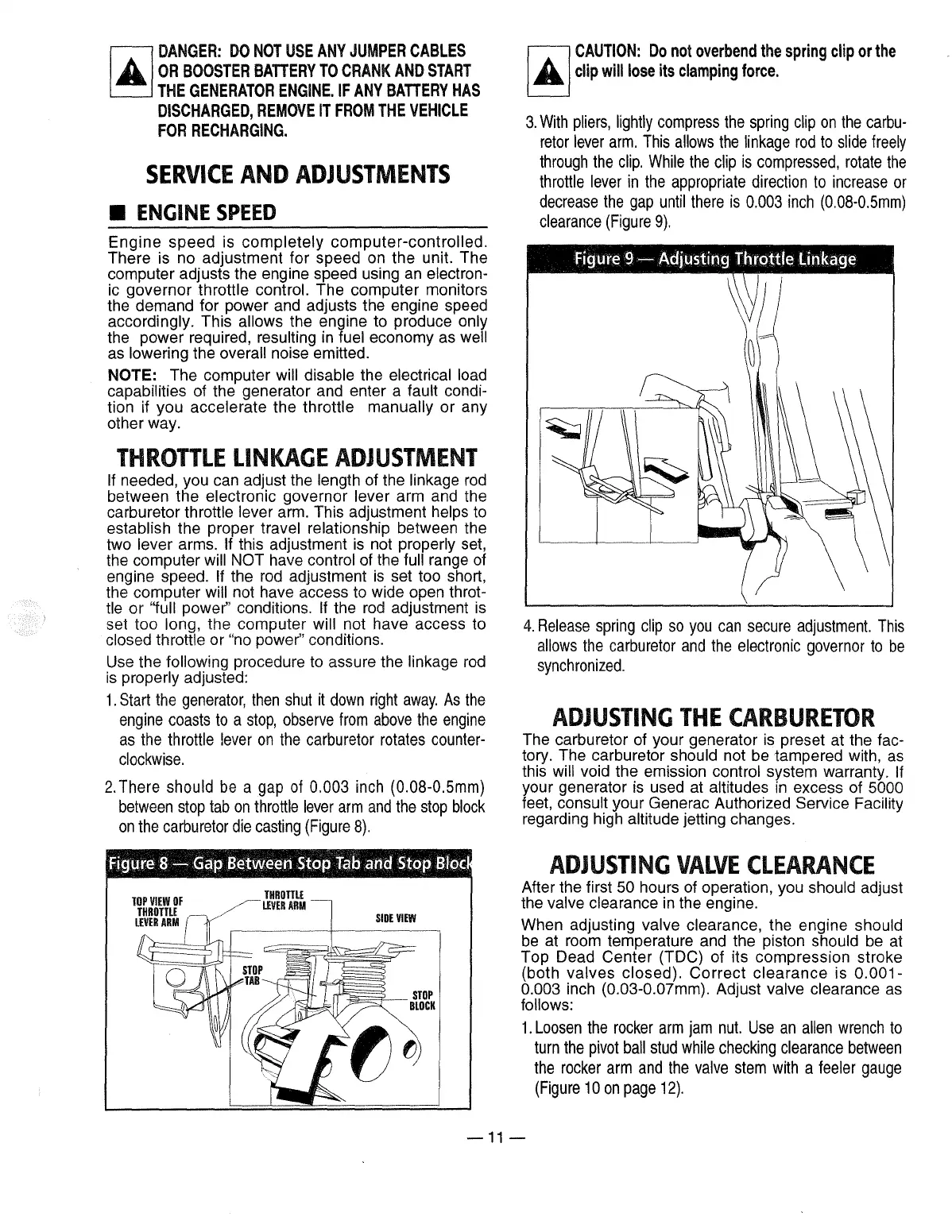
3.
With
pliers,
lightly
compress
the
spring
clip
on
the
carbu-
retor
lever
arm.
This
allows
the
linkage
rod
to
slide
freely
through
the
clip.
While
the
clip
is
compressed,
rotate
the
throttle
lever
in
the
appropriate direction
to
increase
or
decrease
the
gap
until
there
is
0.003
inch
(0.08-0.5mm)
clearance
(Figure
9).
4.
Release
spring
clip
so
you
can
secure
adjustment.
This
allows
the
carburetor
and
the
electronic governor
to
be
synchronized.
ADJUSTING
THE
CARBURETOR
The carburetor of your generator is preset at the fac-
tory. The carburetor should not be tampered with, as
this
will void the emission control system warranty.
If
your generator is used at altitudes
in
excess of 5000
feet, consult your Generac Authorized Service Facility
regarding high altitude jetting changes.
ADJUSTING
VALVE
CLEARANCE
After the first 50 hours of operation, you should adjust
the valve clearance
in
the engine.
When adjusting valve clearance, the engine should
be at room temperature and the piston should be at
Top Dead Center (TDC) of its compression stroke
(both
valves
closed).
Correct
clearance
is
0.001-
0.003 inch (0.03-0.0?mm). Adjust valve clearance as
follows:
1.
Loosen
the
rocker
arm
jam
nut.
Use
an
allen
wrench
to
turn
the
pivot
ball
stud
while
checking clearance
between
the
rocker
arm
and
the
valve
stem
with
a feeler
gauge
(Figure
1 0
on
page
12).
-11-
 Loading...