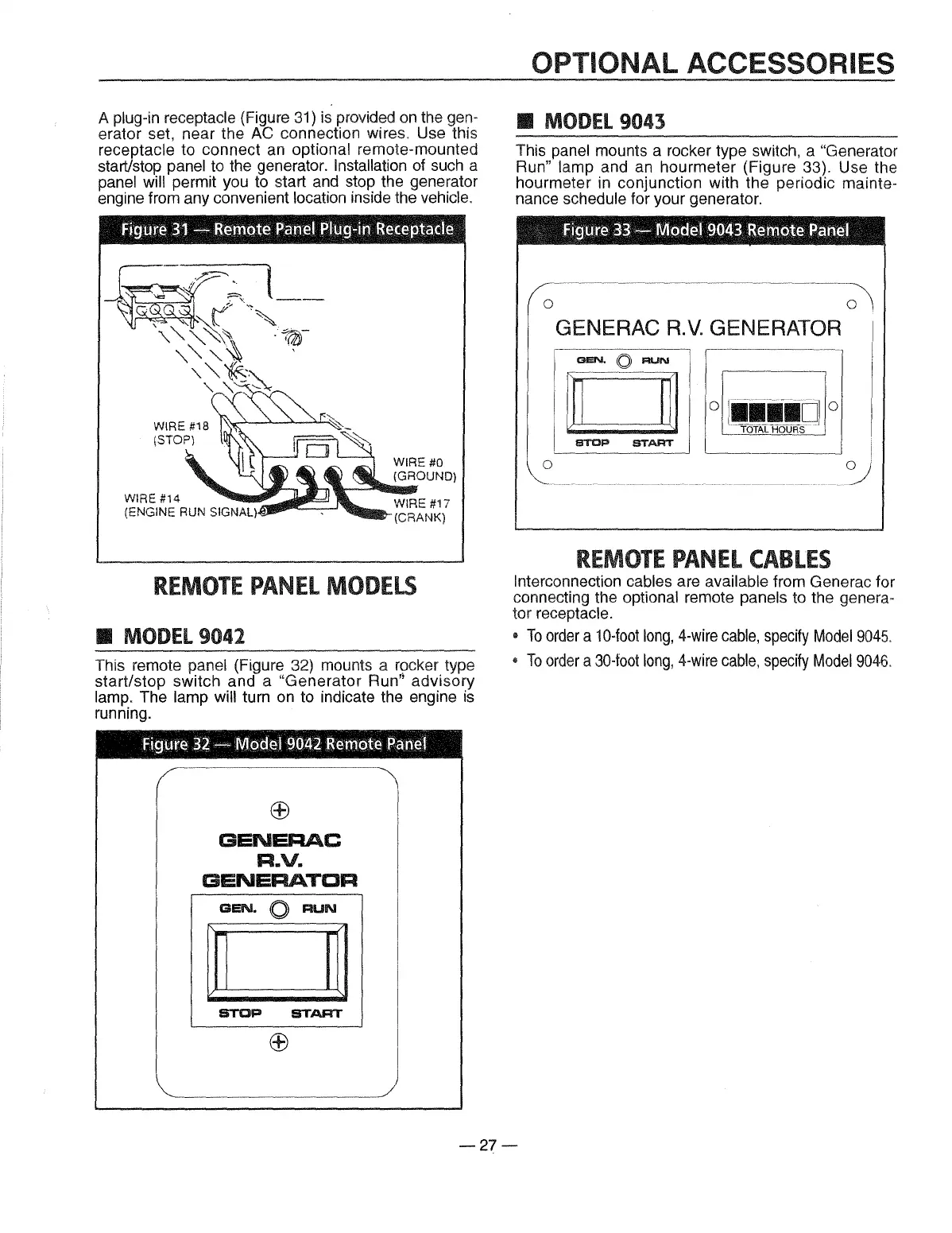
A plug-in receptacle (Figure
31)
is
provided
on
the gen-
erator set, near the AC connection wires. Use this
receptacle to connect
an
optional remote-mounted
start/stop panel to the generator.
Installation
of
such a
panel
will permit you to start and stop the generator
engine from any convenient location inside the
vehicle.
Figurce
91-
Remate
Panel
Plug-in
Reoegtac::le
REMOTE
PANEL
MODELS
• MODEL9042
This remote panel (Figure 32) mounts a rocker type
start/stop switch and a
"Generator Run" advisory
lamp. The lamp
will turn
on
to indicate the engine
is
running.
Figure
32
-
l'lllaclel
9f.nli2.
Remate
Panel
®
GENERAC
R.V.
GENERATOR
GEN.
0
RUN
STOP
START
OPTIONAL ACCESSORIES
• MODEL9043
This panel mounts a rocker type switch, a "Generator
Run"
lamp and an hourmeter (Figure 33). Use the
hourmeter in conjunction with the periodic
mainte-
nance schedule for your generator.
Figure
33-
rvtadel9043
Remote
Pamel
0
GENERAC
R.V.
GENERATOR
0
REMOTE
PANEL
CABLES
Interconnection cables are available from Generac for
connecting the optional remote panels to the
genera-
tor receptacle.
•
To
order
a
10-foot
long,
4-wire
cable,
specify
Model9045
.
•
To
order
a
30-foot
long,
4-wire
cable,
specify
Model9046.
-27-
 Loading...