COOLING AND VENTILATING AIR
It
is absolutely essential that an adequate flow of air
for
cooling, ventilating and engine combustion
be
sup-
plied to the generator
set
Without sufficient air flow,
the engine-generator quickly overheats. Such over-
heating can cause serious operating difficulties and
may
also cause fire and personal injury. The installer
must make sure that sufficient air
is
available to the
generator for
cooling, ventilating and combustion. The
installer must also provide for a path for exhausting
the
cooling air to the exterior of a compartment,
if
so
equipped.
DANGER:
NEVER
USE
DISCHARGED
COOLING
AIR
FOR
HEATING
OR
PERMIT
SUCH
AIR
TO
ENTER
THE
VEHICLE
INTERIOR.
AIR
TAINS
DEADLY
CARBON
MONOXIDE
GAS
AND
OTHER
POISONOUS,
FLAMMABLE
OR
EXPLO·
SIVEGASES.
GENERATOR
AIR
FLOW
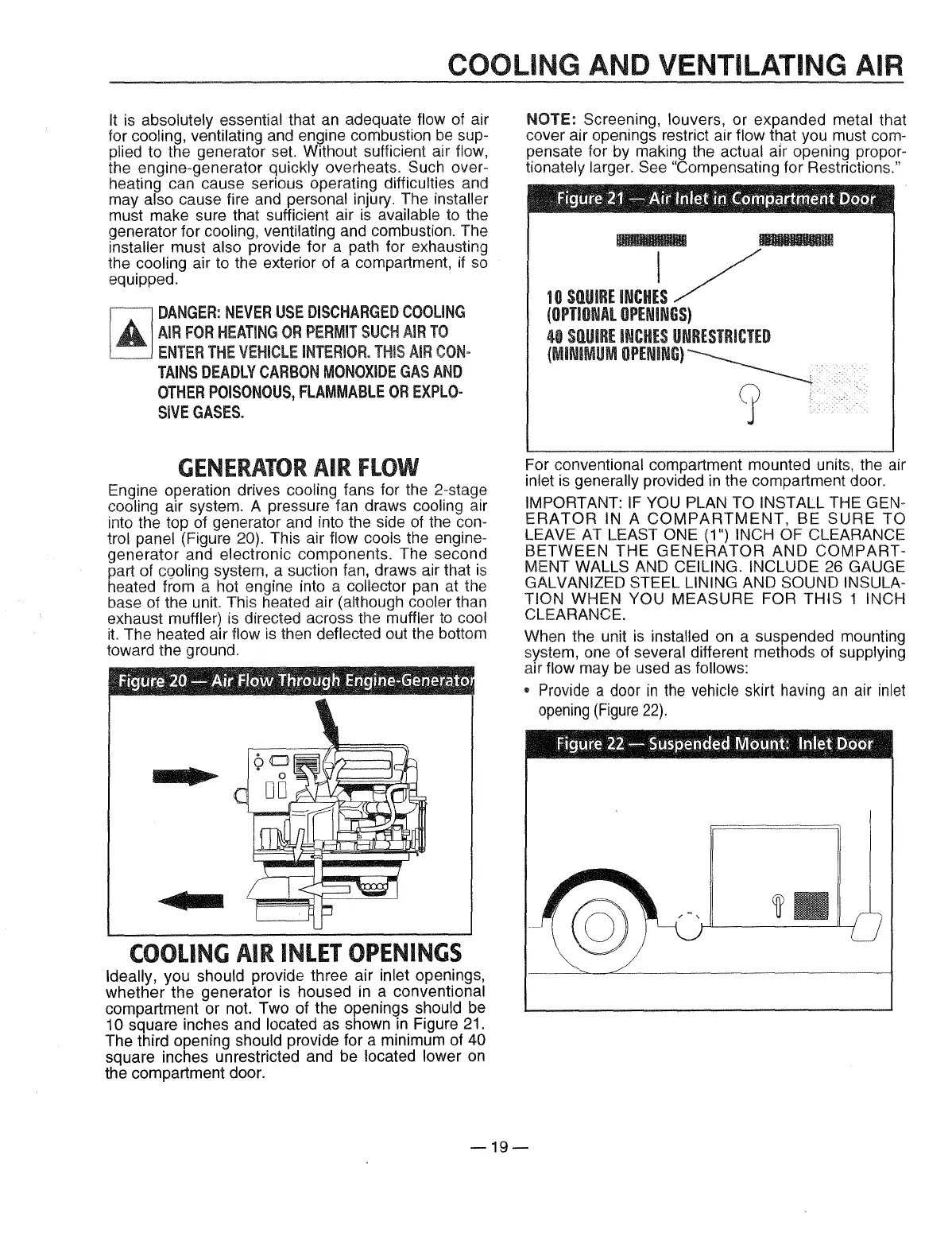
Engine operation drives cooling fans for the 2-stage
cooling air system. A pressure tan draws cooling air
into the top of generator and into the side of the con-
trol panel (Figure 20). This air flow cools the engine-
generator and electronic components. The second
part of
cgoling system, a suction fan, draws air that
is
heated from a hot engine into a collector pan at the
base
of the unit. This heated air (although cooler than
exhaust
muffler)
is
directed across the muffler
to
cool
it.
The heated air flow
is
then deflected out the bottom
toward the ground.
ffiSure
20-
~irfFIC!lW
~t;f~C!lagtit
Engime-~er:nnr"8tJ.~
. . .
COOLING
AIR
INLET
OPENINGS
Ideally, you should provide three air inlet openings,
whether the generator is housed
in
a conventional
compartment or not. Two of the openings
should be
10 square inches and located as shown
in
Figure 21.
The third opening
should provide for a minimum of 40
square inches unrestricted and be located lower
on
the compartment door.
NOTE: Screening, louvers, or expanded metal that
cover air openings restrict air
flow that you must com-
pensate for by making the
actual air opening propor-
tionately larger. See "Compensating for Restrictions."
Aiiilllll
10
SQUIRE
INCHJS
/
(OPTIONAL
OPENINGS)
40
SQUIRE
INCHES
UNRESTRICTED
(MINIMUM
OPENING)~
9 I
For conventional compartment mounted units, the air
inlet
is
generally provided
in
the compartment door.
IMPORTANT:
IF
YOU PLAN TO INSTALL THE GEN-
ERATOR
IN A
COMPARTMENT,
BE
SURE
TO
LEAVE AT LEAST ONE (1") INCH OF CLEARANCE
BETWEEN
THE
GENERATOR
AND
COMPART-
MENT WALLS AND CEILING. INCLUDE 26 GAUGE
GALVANIZED STEEL LINING AND SOUND INSULA-
TION
WHEN YOU
MEASURE
FOR
THIS
1 INCH
CLEARANCE.
When the unit
is
installed on a suspended mounting
system, one of
several different methods of supplying
air flow may
be
used
as
follows:
"
Provide
a
door
in
the
vehicle
skirt
having
an
air
inlet
opening
(Figure
22).
-19-
 Loading...