Unpacking and Inspection
Installation Guidelines for 60 Hz PowerPact™ 9
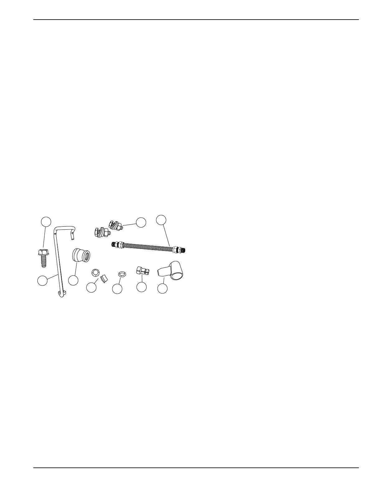
Parts Shipped Loose
See Figure 2-3. Parts shipped loose are located in a
clear plastic bag inside the unit, in front of the engine or
under the alternator. The flex fuel line (A) is tied to either
the battery wires or the alternator can.
• Flex Fuel Line (A)
• Battery Terminal Cap (B)
• LP Fuel Jet (C)
• Fuel Jet O-ring (D)
• Decal - Service Entrance (Not Shown)
• Decal - Warning (Not Shown)
• MLCB Terminal Caps (E)
• Owner’s and Installation Manual (Not Shown)
• Battery Bracket (F)
• M6 x 1 16mm Thread Forming Screw (for Battery
Bracket) (G)
• 2 sets of Bolts, Nuts and Washers (for connecting
battery cables) (H)
• Reducer coupling FNPT 3/4” to 1/2” (J)
Figure 2-3. Parts Shipped Loose
 Loading...