Electrical Connections
Installation Guidelines for 60 Hz PowerPact™ 25
Section 6: Electrical Connections
Control Wiring
* Must be connected to keep battery charged whether unit is
running or not.
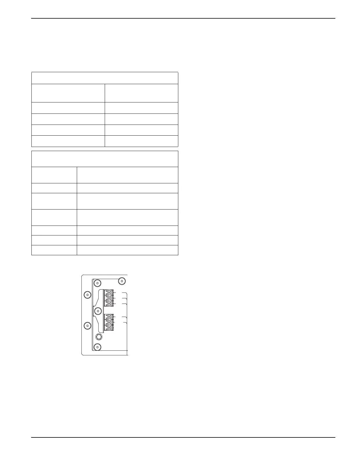
Figure 6-1. Control Wiring
NOTE: Control wiring must be in accordance with local
jurisdiction and codes.
1. Remove the plug from the field connection box.
2. Remove the two hex socket screws to remove the
electrical access panel. The access panel will hang
off of the grounding wire.
NOTE: Do not pull the panel. This will cause the ground
wire to detach from the grounding bus bar.
3. Install the conduit and Main AC and Control Wires
between the generator and the transfer switch
(Figure 6-2). Route the conduit through a NEMA 3
rated external connection box (not supplied).
NOTE: The Electrical access panel is grounded to the
ground bar through a grounding wire. Verify the integrity
of this connection before closing the panel back.
NOTE: This wiring can be run in the same conduit if the
appropriate insulation rated wire is used.
4. Seal the conduit at the generator and in
compliance with any codes.
5. Strip the insulation from the ends of the wires. Do
not remove excessive insulation.
6. To connect the control wires, push down on the
spring loaded connection point with a flat head
screwdriver, insert wire and release.
NOTE: No wire insulation should be in the connection
point; only bare wire.
Control Wire Recommended Length and Size
Maximum Wire Length Recommended Wire
Size
1–115 ft (0.3–35 m) No. 18 AWG
116–185 ft (36–56 m) No. 16 AWG
186–295 ft (57–89 m) No. 14 AWG
296–460 ft (90–140 m) No. 12 AWG
Table 6-1. Customer Wiring Connections
Integrated PCB (non-SACM)
Terminal
Numbering Decal
Wire Numbers
BLUE* T1—Fused 120 VAC for battery charger
YELLOW
N1—Fused 240 VAC
Sensing for utility dropout and pickup
YELLOW WITH
BLACK STRIPE
N2—Fused 240 VAC
Sensing for utility dropout and pickup
BLACK 0—DC (-) Not required
RED 194—DC (+) 12 VDC for transfer controls
WHITE 23—Transfer control signal wire

 Loading...