Installing PWRcell Battery
16 Installation Manual for Generac PWRcell Battery
Installing Foot Bracket (OR model only)
Mount foot bracket to wall with the following procedure:
A template is included and will help locate the holes for
both Wall and Foot Brackets.
• Before finalizing horizontal location for upper and
lower wall mount, ensure all bolts will line up with
wall studs.
• Lower mount should maintain of distance of 3 in
minimum from grade.
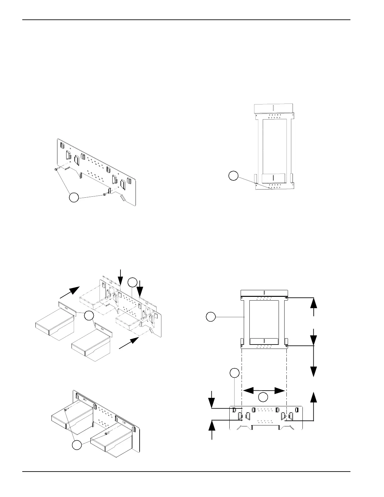
• See Figure 4-1. Install the lower wall mount with flat
washers and lag bolts (A).
NOTE: Do not install the top bolts at this stage. This will
inhibit foot bracket installation.
Figure 4-1. Install Lower Wall Mount
• See Figure 4-2. Slide foot bracket (A) into bottom
bracket (B) making sure underside of pockets clear
bottom bracket before engagement. Proper
installation is achieved by lining up the top edge of
lower wall mount to the bottom edge of wall flange
part of foot bracket.
Figure 4-2. Insert Foot Bracket into Lower Mount
• See Figure 4-3. Use flat washers and lag bolts (A)
to secure top of lower mount.
Figure 4-3. Install Top Bolts in Lower Wall Mount
Installing Wall Bracket
•
See Figure 4-4. Bottom edge (A) is 29-5/8 in (752
mm) off the floor for IR installations.
• Each horizontal brace requires a minimum of two
fasteners. Four total fasteners are required. All
fasteners must engage structural materials by a
minimum of 1.5 in. All fasteners must be field
supplied. Installer must ensure that fasteners
selected are appropriately rated for this application.
Figure 4-4. Wall Bracket
For OR installations, mount wall bracket to wall with the
following procedure:
• See Figure 4-5. Once the lower wall mount is
installed make sure the mounting holes to the lower
wall mount (B) line up with the upper wall mount (A)
for 16 in on center studs (C). Four screws are
required in lower wall mount.
• Be sure to maintain 34 7/8 in (886 mm) spacing
between bottom holes in upper wall mount and
bottom holes in lower wall mount.
Figure 4-5. Lower and Top Bracket Alignment
A
011153
011155
A
B
011156
A
009920
A
011154
34 7/8 in
(886 mm)
A
B
C
16 in
(406.4 mm)
4 3/16 in
(106.8 mm)
17 3/16 in
436 mm

 Loading...