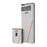
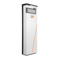
Installing PWRcell Battery
Installation Manual for Generac PWRcell Battery 25
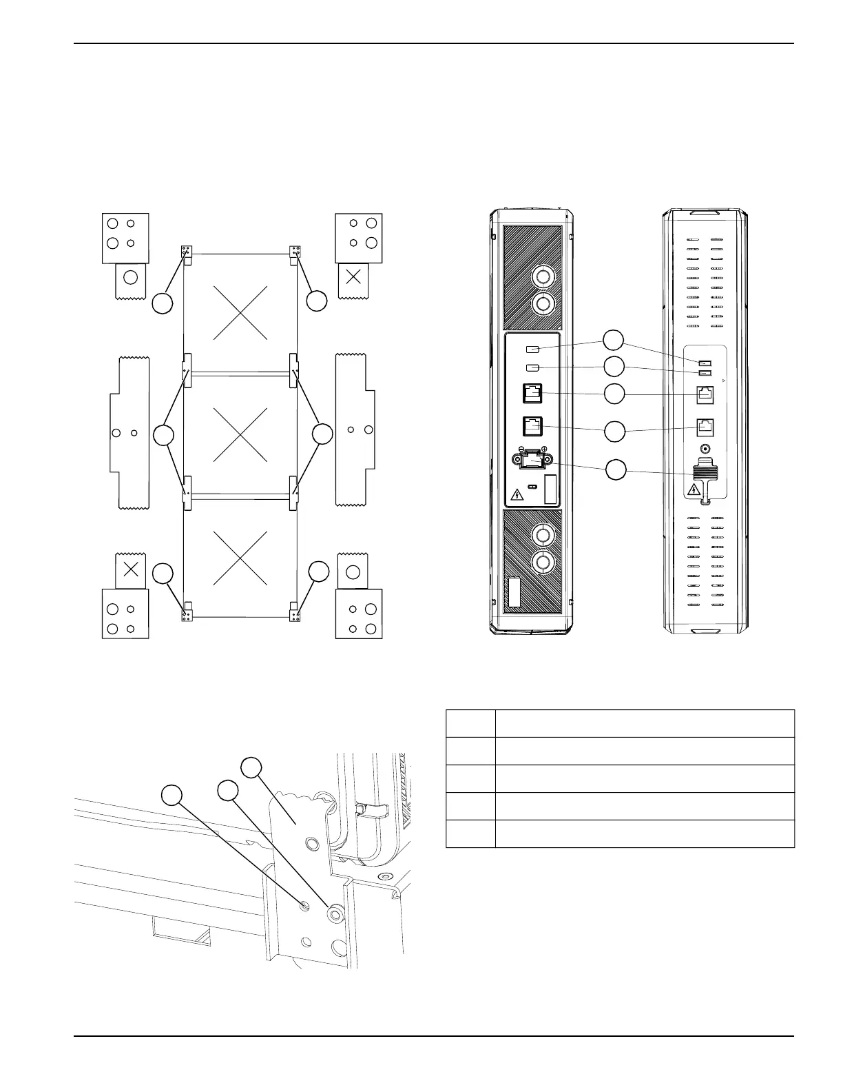
See Figure 4-27. Note that there are three types of
retainer clips: double retention clips (U), single retention
clips marked O (T) and single retention clips marked X
(S).
• Install single retention clips (T) (S) at the top and
bottom of the stack.
• Install double retention clips (U) between rows of
modules.
Figure 4-27. Installing Retention Clips (2 of 3)
To install retention clips:
1. See Figure 4-28. Align holes in retention clip (V)
with stud (W) and mounting hole (X).
Figure 4-28. Retention Clips (3 of 3)
2. Apply gentle pressure to ensure all grounding tabs
and clips make firm contact with case.
3. Secure retention clip to bracket with a M4X8 mm
screw and torque to 13 in-lb (1.47 Nm).
Connecting COM Cables (DCB and EX
Modules)
See Figure 4-29 for a description of the module connec-
tions and indicator lights.
Figure 4-29. DCB (left) and EX Module (right)
Connections
1. See Figure 4-30. Locate multicolored CAT5 cables
attached to battery power cable harness on body
(Y) and top, rear battery module (Z).
2. Connect Gray CAT5 cable to battery module COM
IN (A)
3. Connect Black CAT5 jumper to battery module
COM OUT (B).
NOTE: Black CAT5 jumper is found in hardware kit.
T
U
U
T
S
S
009938
V
W
X
009939
A Battery Connection Power Port
B CommOut Port
C CommIn Port
D SoC LED
E Status LED
SOC
STATUS
COM IN
COM OUT
Status
SOC
CommIn
CommOut
-
+
WARNING CANCER AND REPRODUCTIVE HARM - www.P65Warnings.ca.gov.
C
B
A
012286
D
E
 Loading...