Installing PWRcell Battery
26 Installation Manual for Generac PWRcell Battery
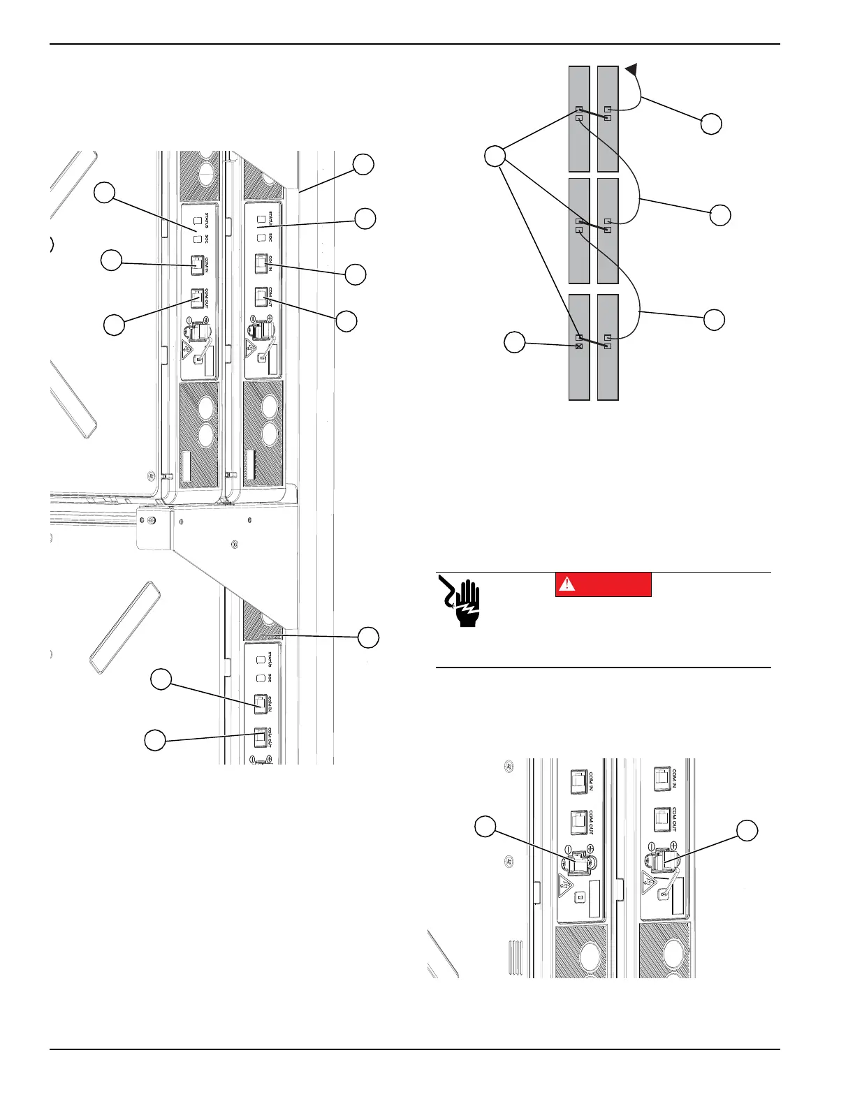
4. Connect the other end of Black CAT5 jumper to
COM IN port (D) on front battery module (C).
5. Connect Blue CAT5 cable to COM OUT port (E).
6. Connect the other end of Blue CAT5 cable to COM
IN port (G) on lower, rear battery module (F).
Figure 4-30. Module COM Cabling (1 of 2)
7. See Figure 4-31. Continue connecting the remain-
ing battery modules. While installing CAT5 cables:
• Work from top to bottom.
• Connect battery modules sharing a shelf with a
black jumper cable (L) going from the rear battery
COM OUT port to the front battery COM IN port.
• Do not install a CAT5 cable to the last battery
module’s COM OUT port (M).
• Remaining COM cables can be left disconnected.
• Unused CAT5 jumpers should be kept in safe place
for future module upgrades.
Figure 4-31. Module COM Cabling (2 of 2)
Connecting Battery Power Cables
1. See Figure 4-32. Remove gray rubber cap (A)
from each module power port.
2. Plug black power cable connectors into battery
module power ports (B).
Figure 4-32. Power Cable Ports
009940
B
D
Z
A
E
C
F
G
H
Y
I Gray CAT5
J Blue CAT5
K Orange CAT5
L Black CAT5 Jumpers
009941
M
L
I
K
J
Electrocution. Never reach into port or touch
battery terminals with hands or tools. Doing so
will result in death, serious injury, equipment or
property damage.
DANGER
(000639)
A
B
009942
 Loading...