Installing PWRcell Battery
Installation Manual for Generac PWRcell Battery 23
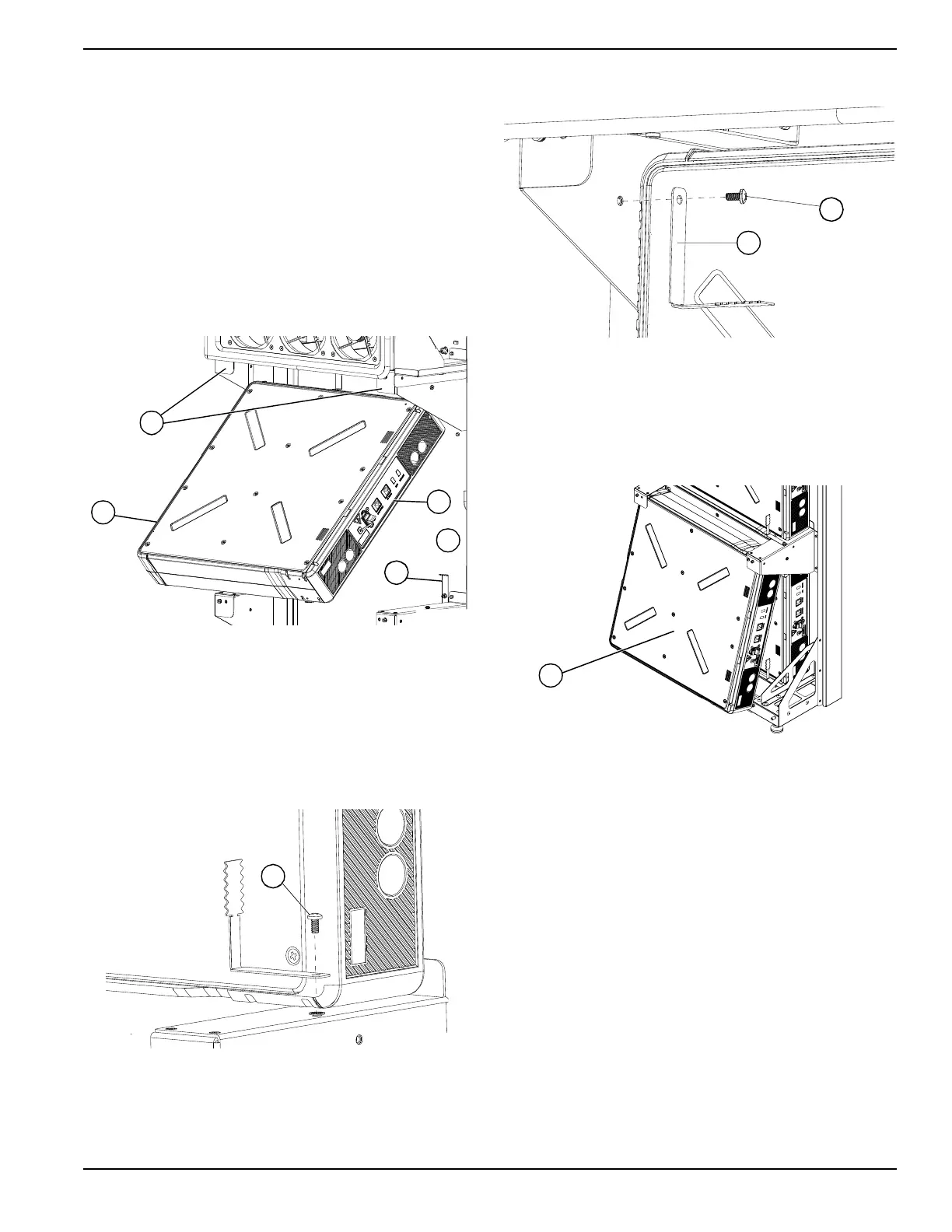
Installing Rear Modules
1. See Figure 4-18. Angle top of battery module (G)
under and behind bracket lip (H).
IMPORTANT NOTE: Battery module ports (I) must
face the right side of the PWRcell Battery body with
the COM ports above the power port.
2. Slide bottom of module to back of PWRcell Battery
chassis (J).
3. Push bottom of module against grounding clips (K).
NOTE: Grounding clips are designed to contact and bite
into the battery module case to provide an equipment
grounding connection.
Figure 4-18. Installing Rear Battery Modules
Installing Grounding Tabs
1. See Figure 4-19. Install two L-shaped grounding
tabs (L) at the bottom of the module on both sides.
2. Fasten each grounding tab with a M4x8 mm SEMS
screw (M) torque to 13 in-lb (1.47 Nm).
Figure 4-19. Installing Bottom Grounding Tabs
3. See Figure 4-20. Install grounding tabs (L) at the
top of the module on both sides.
4. Fasten each grounding tab with a M4x8 mm SEMS
screw (M) and torque to 13 in-lb (1.47 Nm).
Figure 4-20. Installing Top Grounding Tabs
Installing Front Modules
See Figure 4-21. Install front battery modules (N) using
the same procedure as used on the rear modules. See
Figure 4-17. Battery Module / Spacer Order of Instal-
lation.
Figure 4-21. Installing Front Battery Modules
Installing Module Spacer (PWRcell M3 and
PWRcell M5 only)
See Figure 4-22. Module spacers (O) must be installed
on any single module shelf.
G
H
K
J
I
009929
M
009930
M
L
009931
N
009932

 Loading...