Electrical Connections
Installation Manual for Generac PWRCell Inverter 21
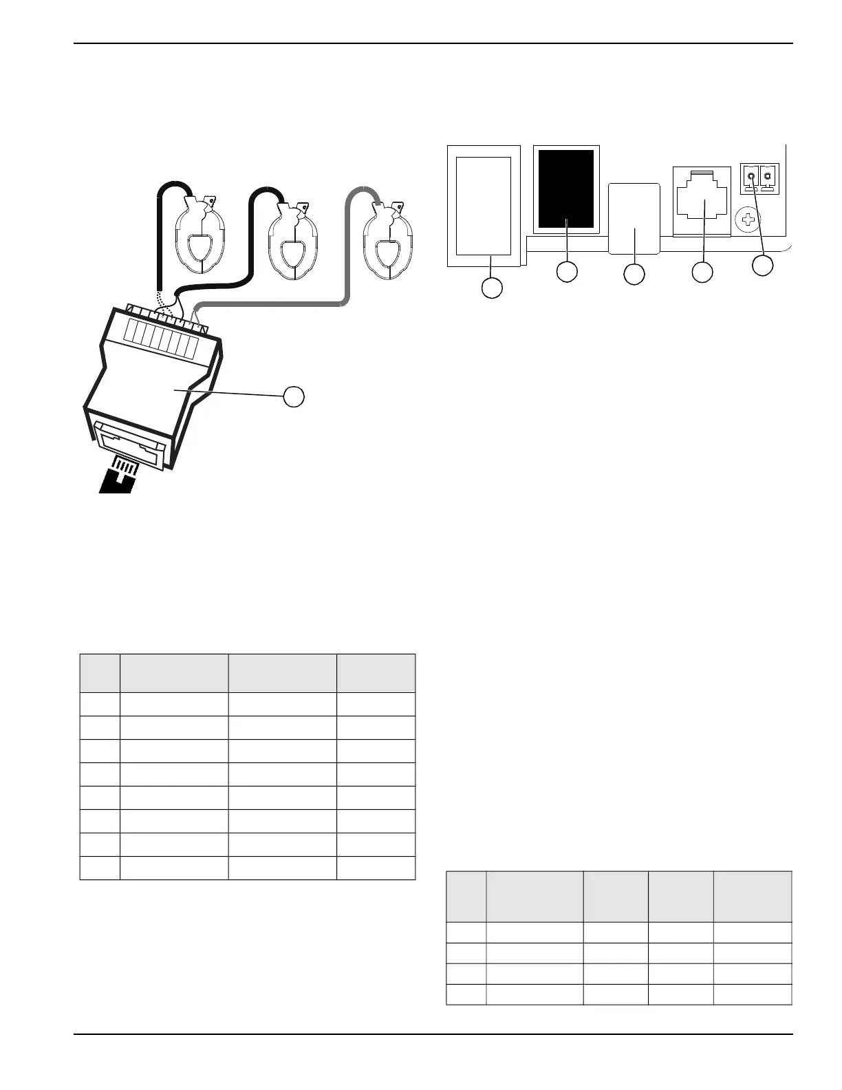
Connecting CTs to the Inverter
1. See Figure 5-8. Connect CT leads to RJ-45 Break-
out Adapter’s (M) push terminals according to the
label on the breakout adapter.
NOTE: Use yellow lead for CTx+ and use green lead for
CTx-.
Figure 5-8. RJ-45 Breakout Adapter
NOTE: RJ-45 Breakout Adapter is included in the
Generac PWRcell Kit.
NOTE: If the RJ-45 Breakout Adapter is not available,
the CT leads can be wired to a Category 5 (Cat 5) cable.
Use Table 5-8 to wire CTs directly to stripped Cat 5 wire.
2. See Figure 5-9. Connect Cat 5 cable to CT input
jack (H).
NOTE: The connection between the RJ-45 breakout
adapter and the inverter is made using a widely available
installer supplied Cat 5 style cable.
• CT input jack is a double-stacked RJ-45 jack.
• Either the top or bottom port may be used.
• Both jacks may be used when multiple sets of
CTs are required.
:
Figure 5-9. Accessory Ports
NOTE: When setting an ESS Grid Usage Mode other
than the default unrestricted mode, attach the label
packaged with the CTs to the inverter.
Connecting Multiple Sets of CTs
When installing CTs, local factors may require multiple
sets of CTs to fully measure the utility power being sent to
the building.
For 4-wire, 120 / 240 VAC, split-phase service:
• Use two pairs of CTs to measure the service. Use
each pair of CTs to measure a pair of service
conductors / feeders within the main panel.
• Use both RJ-45 jacks with two Cat 5 cables.
• Connect CT1 from both cables to the same phase
and CT2 cable from both cables to the second
phase.
• See Table 5-9: Multiple CT Connection. Connect
Cat 5 cables from the adapters into the two CT
accessory ports at the inverter.
NOTE: Make sure to use the same pinout and
connections.
Table 5-8. CT RJ-45 Pinout
Pin
Wire Color
(T-568A)
Wire Color
(T-568B)
Value
1 White / Green White / Orange CT3+
2 Green Orange CT3-
3 White/Orange White / Green CT2+
4 Blue Blue CT1+
5 White / Blue White / Blue CT1-
6 Orange Green CT2-
7 White / Brown White / Brown Not Used
8 Brown Brown Not Used
NA
NA
CT2 ‒
CT1 ‒
CT1+
CT2+
CT3 ‒
CT3+
010222
M
H Current Transformers (CTs) Accessory Port (RJ-45)
I Automatic Transfer Switches (ATS) Accessory Port
(RJ-45)
J REbus Beacon Port (USB-B)
K Authorized Generac Personnel Only
L STOP Terminals
Table 5-9. Multiple CT Connection
CT
Service
Phase and
Wire Adapter
Adapter Adapter
Pins
CT Port
Row
Values
1-1 L1-1 1 4 and 5 Front Port
1-2 L2-1 1 3 and 6 Front Port
2-1 L1-2 2 4 and 5 Back Port
2-2 L2-2 2 3 and 6 Back Port
010001
H
I
J
K
L
 Loading...