Model 2180A
4
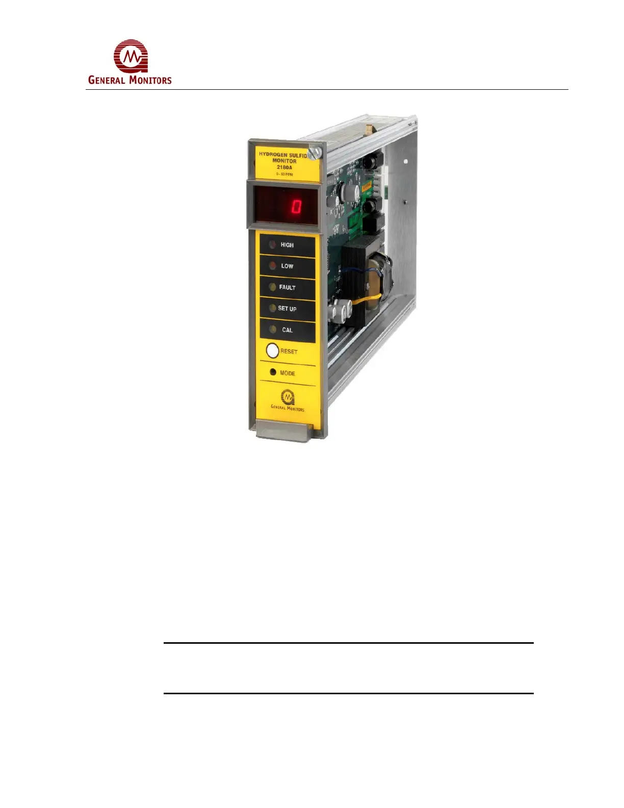
Figure 1: Model 2180A
1.3 Controller
The unit has:
• Sensor Circuit
• LED indicators for High, Low, Fault, Calibration, and Setup
• Mode Button, accessed by using a small screw driver
• Digital Display in ppm
• High, Low & Fault relays
NOTE: A service-loop is necessary between the Model 2180A Controller’s rear
panel terminals and field/power wiring. This service loop permits the
controller to be removed or slid forward for servicing. This service loop is
a definite advantage when replacing or changing a controller.