Model 2180A
17
3.4 Analog Output
The Analog Output is a 0 to 21.7mA current signal with 4 to 20mA being proportional to 0
to 100% of full scale.
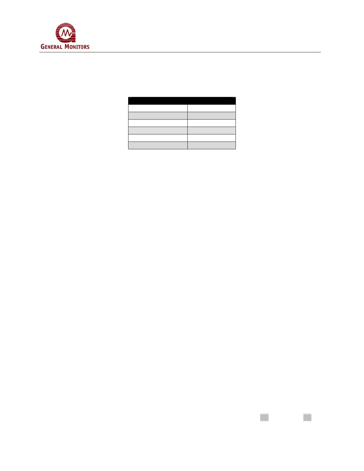
Analog Output Values
Signal Range 4-22mA
Fault <1.0mA
Start-up 4mA
Calibration 1.5mA
Detection Range 4-20mA
Over-Range 20 – 21.7mA
When a channel is in the Calibration, Calibration Check, Setup, or Setup Check modes, a
1.5mA signal is generated by this output. During Calibration mode the digital display
shows prompts associated with the calibration procedure. During Calibration Check
mode, the digital display shows the gas concentration as a flashing digit, or pair of digits.
When the channel enters into a Fault condition a 0mA signal is generated by this output.
If the sensor sees gas in excess of 100% of full scale, the output generates a signal
between 20 and 21.7mA (not proportional).
3.5 Calibration Preparation Instructions
Before a full calibration or calibration check is begun, ensure the sensing assembly is
seeing “clean air”. If the atmosphere at the sensor contains a low background of H
2
S
observe the following procedure.
1. Obtain a GMI field calibrator plastic bottle (P/N 50000). Assure that it contains no H
2
S
by flushing it with clean air. Place your hand or a cover over the bottle’s open end
and take it to the sensor.
2. Place the bottle over the sensor.
3. Wait a few minutes for the sensor to become permeated with clean air.
4. Remove the sensor from the bottle.
After each use of the field calibrator bottle, clear the bottle of residual H
2
S gas by flushing
it with clean air.
3.5.1 Gas Application Options
3.5.1.1 Breaker Bottles and Ampoules
General Monitors offers ampoules with breaker bottles as a method of reliably introducing
calibration gas to the Model 2180A. The ampoule is placed inside the breaker bottle into
the breaker slot, and the breaker bottle is placed over the sensor. The ampoule should
contain 50% FS of H
2
S of the sensor range. For example, for 100ppm full scale use a
50ppm ampoule. Check the date code on the ampoule to make sure the expiration date
has not passed. Follow the calibration procedure below in Section 3.6 and Section 3.7.