Model 2180A
11
NOTE: Shielded cable should be grounded only at the controller, using the ground
terminal provided. Care should be taken to insure that the outer braid does not
have contact with the conduit or junction box.
2.8 Alarm Wiring Connections
The Model 2180A alarm relays may be operated as normally de-energized or normally
energized, and latching or non-latching.
The Low and High alarm contacts for customer use are DPDT (double pole, double
throw), and are rated 4 amps at 115 VAC, resistive. The Fault alarm contact is SPDT
(single pole, double throw), 4 amps at 115 VAC, resistive. These contacts are brought out
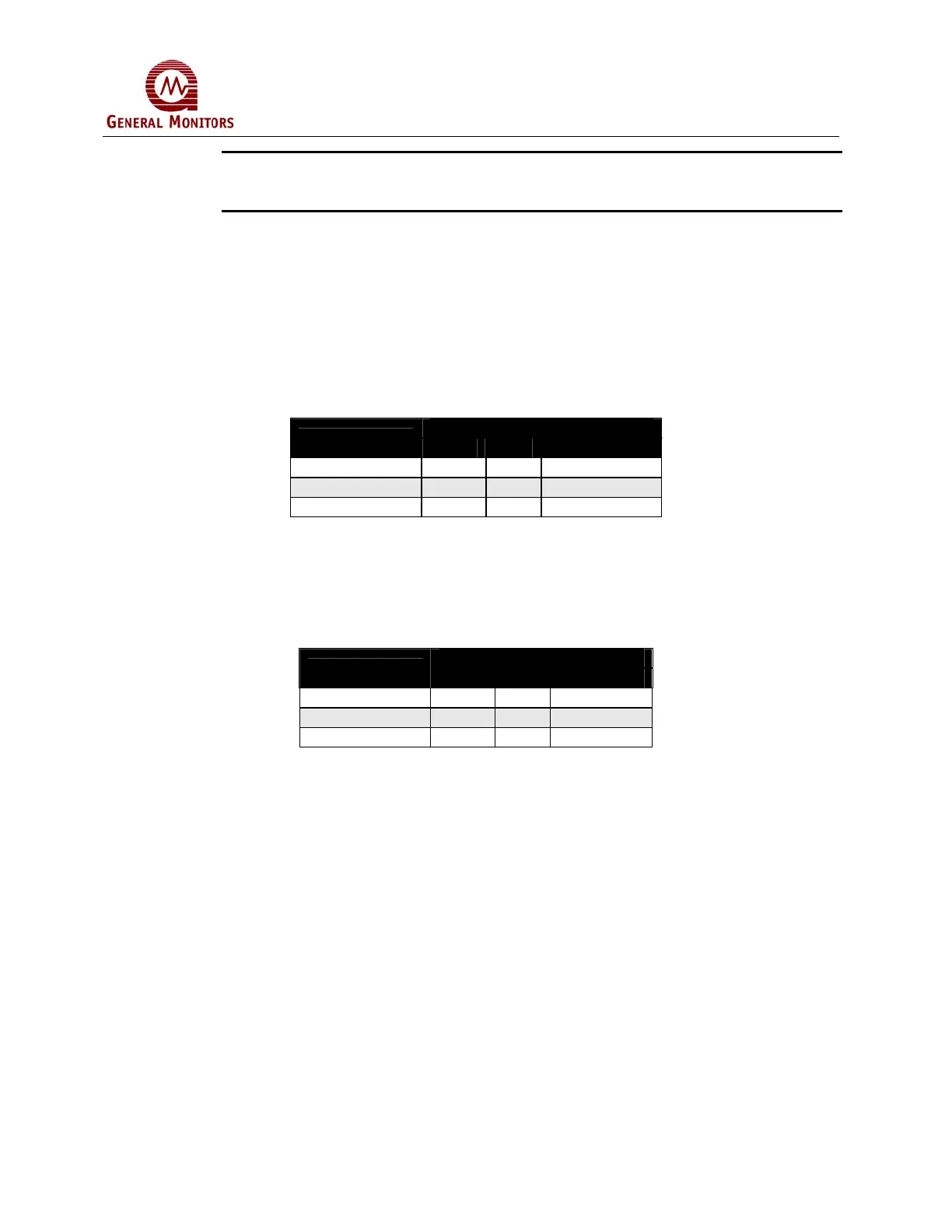
to terminals on the rear of the controller as follows:
CONTACT CONDITION
ALARM RELAY
OPEN COM CLOSED
Fault 1 C 2
Low Alarm 2,3 C 1,4
High Alarm 2,3 C 1,4
Table 5: De-Energized Alarm Relay Contacts
The above chart shows the High and Low alarm contacts in the standard de-energized
state (with power applied). These two alarm relays are normally de-energized unless
specially ordered for normally energized operation. The Fault relay is always supplied
normally energized. If normally energized, the terminations are:
CONTACT CONDITION
ALARM RELAY
OPEN COM CLOSED
Fault 1 C 2
Low Alarm 1,4 C 2,3
High Alarm 1,4 C 2,3
Table 6: Energized Alarm Relay Terminations