Model 2180A
10
To connect the cable to the sensor:
1. Remove the housing lid (P/N 10252-1) to reveal the terminal strip. The sensor is
connected in the housing according to color designations as follows:
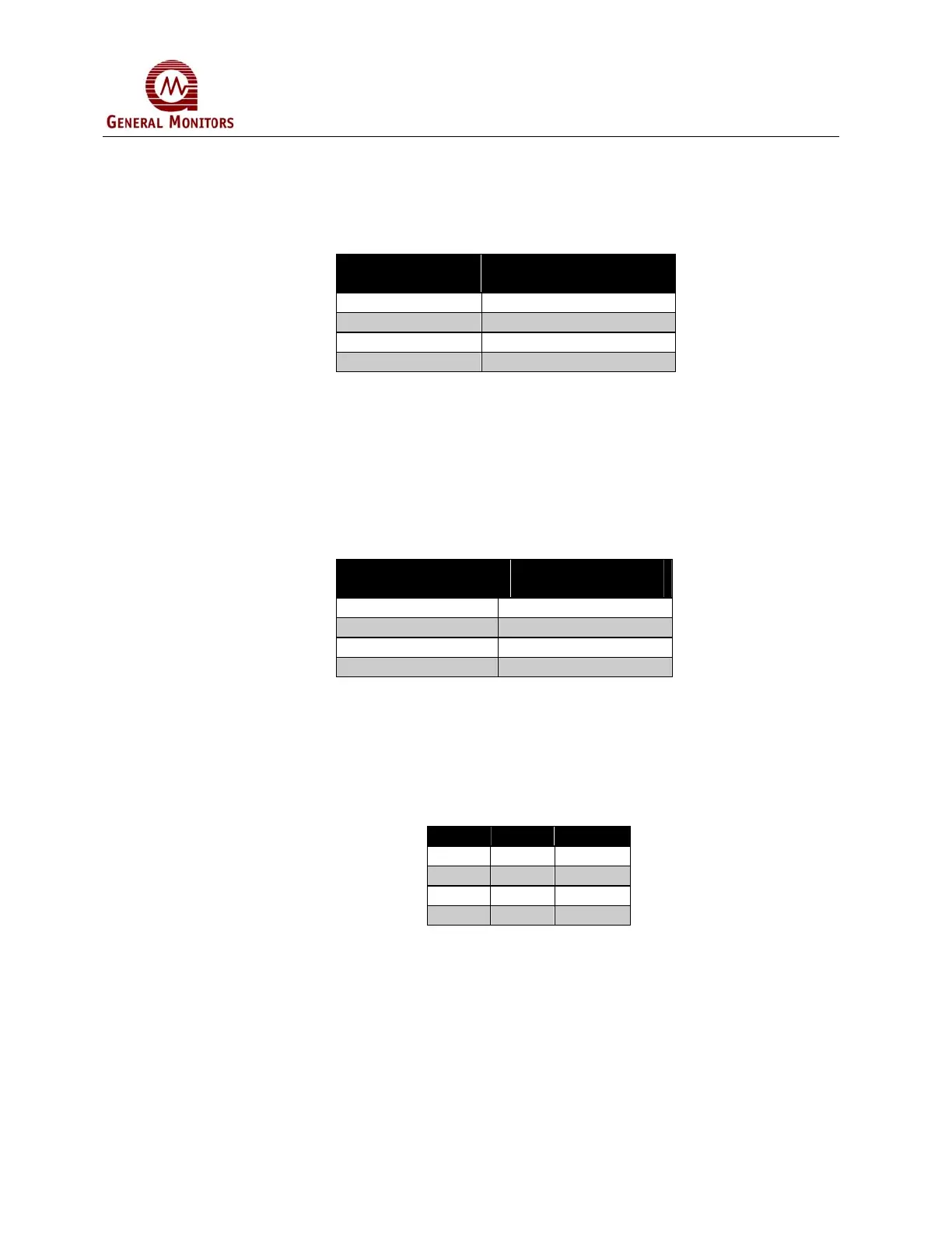
Sensor Housing
Terminal Number
Sensor
Wire Color
1 White
2 Black
3 Red
4 Green
Table 2: Sensor Wire Colors
2. Install the sensor assembly with conduit in hazardous areas. A good design
would include conduit seals to prevent water build-up.
3. Connect the cable so that the terminal color at the sensor housing matches the
terminal color at the controller. General Monitors’ sensor leads are color coded,
and should be connected to the rear terminal connector as shown in the following
table:
Terminal Connector
Sensor Cable
Color
W1 White
B2 Black
R3 Red
G4 Green
Table 3: Sensor Cable Colors
The maximum cable length, using four conductor cable, should be such that the total loop
resistance of any signal path (for example the black leads) does not exceed 20-Ohms at
25º Celsius. The following table may be used as a guide to determine cable length versus
wire size:
AWG Feet Meters
14 3,375 1,030
16 2,250 685
18 1,350 410
20 900 275
Table 4: Cable Length
Two accessories are available which can be supplied with the system, if ordered:
• Splash Guard, P/N 10395-1
• Test Gas Applicator, P/N 10460-2
Both of these products are designed to provide extra protection in problem environments.