Model 2180A
6
2.0 Installation
2.1 Location of the Controller
The Model 2180A controller should be installed in a weather-protected, non-hazardous
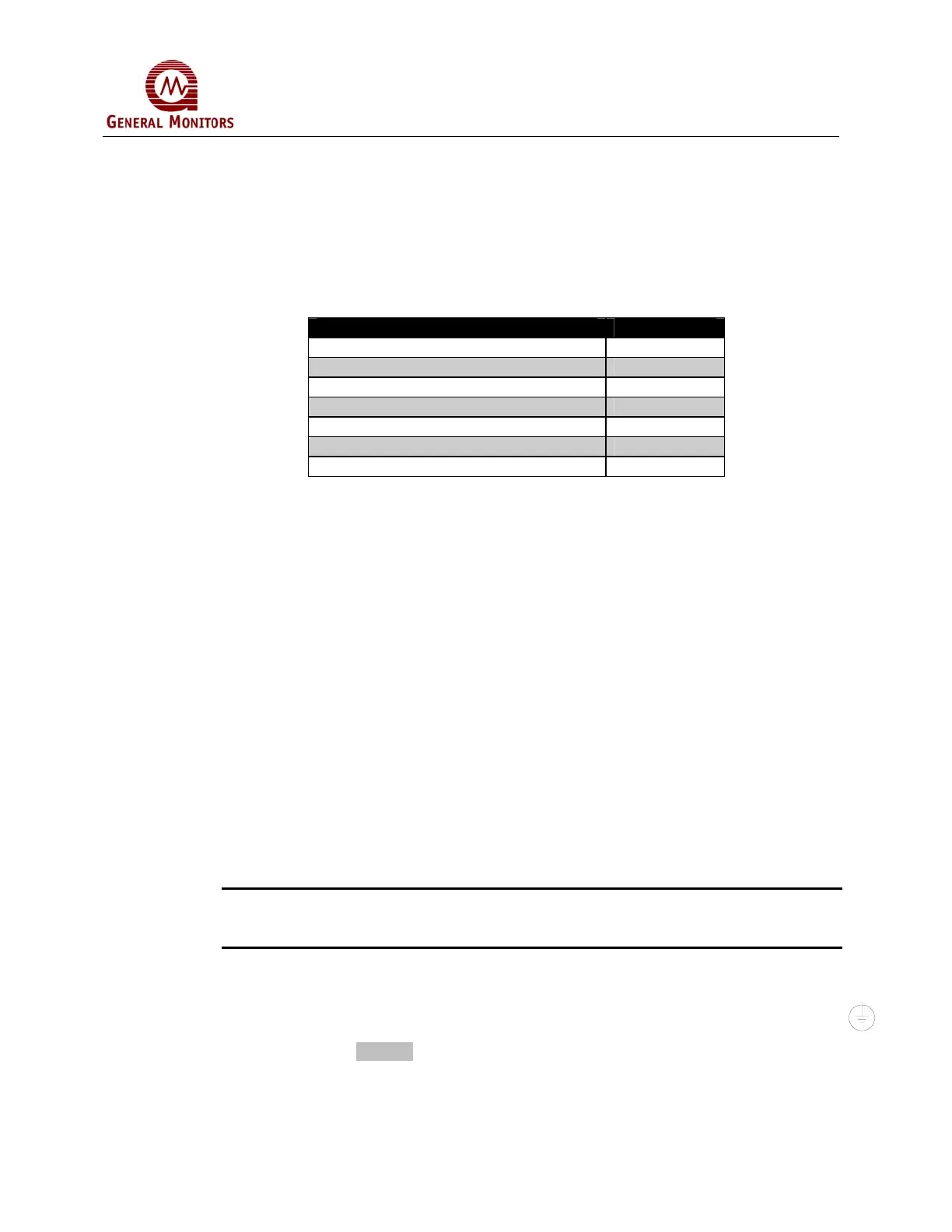
area. The following hardware is available to assist installation:
Part Description Part Number
98 mm (4”) panel mount frame 10199-1
483 mm (19”) rack mount frame 10200-1
98 mm (4”) blank panel 10191-2
98 mm (4”) wall mount bracket 10202-1
Weatherproof enclosure 10259-1
NEMA 7 explosion-proof enclosure 10099
Desk top cabinet (up to four controllers) 914-006
Table 1: Model 2180A Mounting Parts
The following are guidelines for mounting the controller.
• To minimize the possibility of electrical shock, mounting must be as free from
shock and vibration as possible and in a grounded enclosure that requires a tool
for instrument removal.
• Even though the controller is RFI resistant, do not mount the controller in close
proximity to radio transmitters or similar equipment.
• Care should be taken to assure adequate ventilation.
• Do not mount the controller in a manner, which restricts the natural convection
airflow from normal ambient air.
• The controller operating temperature range is 0°C to 60°C (32°F to 140°F).
2.2 Power Connections
The Model 2180A operates on a nominal line voltage of 117 VAC, 50-60 Hz., 220 VAC
operation is an available option.
NOTE: To eliminate accidental shutdown, GMI does not provide a power ON-OFF
switch. Power must remain disconnected until all other wiring connections are
made.
The following are wiring guidelines for the 2180A Controller:
• If AC is to power the system, connect the line power supply to the terminals L, N,
and GND located at the rear of the controller. Use accepted commercial wiring
practices. (Figure 4)
• Primary DC power may be used instead. Use any 24VDC nominal supply with a
minimum rating of 2 amperes.