Models FL3100/3101
ix
Table of Figures
Figure Q-A 961-004 Union Swivel Mounting Hardware.................................iv
Figure Q-B 71172 Rear View Wall Mounting Assembly................................ iv
Figure Q-C 71172 Rear View Bracket Assembly............................................v
Figure Q-D Field Terminations........................................................................v
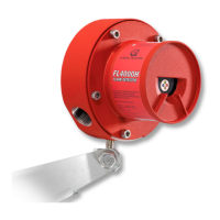
Figure 2-A Model FL3100 .............................................................................1
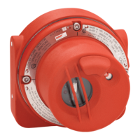
Figure 2-B Model FL3101 ..............................................................................1
Figure 3A-1 FL3100 (UV/IR) Field of View.......................................................3
Figure 3A-2 FL3101 (UV) Field of View...........................................................4
Figure 3A-3 FL3101 (UV) Field of View...........................................................5
Figure 3-B 961-004 Swivel Elbow Drawing
(Class I, Div 1 & 2, Groups C & D)............................................6
Figure 3-C 71072 Mounting Bracket Drawing
(Class I, Div 1 & 2, Groups B, C & D or Zone 1 and 2).............6
Figure 3-D 71072 Mounting Bracket Drawing
(Class I, Div 1 & 2, Groups B, C & D or Zone 1 and 2).............7
Figure 3-E FL3100 & FL3101 Outline Drawing..............................................7
Figure 3-F FL3100 & FL3101 Outline Drawing..............................................8
Figure 3-G FL3100 & Fl3101 Field Terminations...........................................8
Figure 3-H Terminal Designations..................................................................9
Figure 3-I Detector Housing and Base .........................................................9
Figure 3-J Terminal Block Operation...........................................................10
Figure 3-K Protection Circuits for Relay Contacts .......................................10
Figure 4-A Dip Switch Options.....................................................................17
Figure 4-B1 Dip Switch Location....................................................................18
Figure 4-B2 Dip Switch Location....................................................................18
Figure 5-A UV and IR Windows ...................................................................20
Figure 6-A 71100 FL3100 (UV/IR), Final Assembly.....................................25
Figure 6-B 71125 FL3101 (UV), Final Assembly.........................................26
Figure 9-A Spectral Response of UV and IR Detectors...............................44
 Loading...