WEAR SAFETY EYEWEAR AND ANY OTHER
SAFETY APPAREL DEEMED APPROPRIATE
FOR THE JOB APPLICATION AND/OR JOB
SITE ENVIRONMENT. THE BLADE
REPLACEMENT PROCESS CAN CREATE
FLYING STEEL CHIPS AND/OR OTHER
DEBRIS. CAUTION ALL ONLOOKERS
REGARDING THE POSSIBILITY OF AND/OR TO
REMAIN CLEAR OF FLYING DEBRIS.
IMPROPER SAFETY PROCEDURES CAN
RESULT IN PROPERTY DAMAGE AND/OR
PERSONAL INJURY.
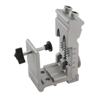
2) Inspect the auger for worn or broken components.
Check to determine that the auger does not have a
bent or damaged axle. A bent or damaged axle will
cause the auger to "wobble" during use. Maximum
allowable auger wobble is 0.25 inch (7 mm) total
indicated runout (TIR). An auger with a total indicated
runout wobble in excess of this value should be
removed from service and scrapped.
DO NOT OPERATE AN AUGER WHICH HAS A
BENT OR DAMAGED AXLE WITH A TOTAL
INDIC ATED RU N OU T EXCEED I N G T H E
MAXIMUM ALLOWABLE LIMIT. EXCESSIVE
AUGER WOBBLE CAN REDUCE OPERATOR
CONTROL, RE S ULTI N G I N PRO PERT Y
DAMAGE AND/OR PERSONAL INJURY.
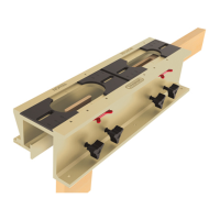
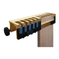
3) Using the 7/16 inch wrenches, loosen the capscrews
to remove the worn blade from the auger plate.
Remove any accumulated dirt from the auger plate
area. Install the replacement blade with the capscrew
threads facing up toward the hub. The replacement
blade will extend past the outside diameter of the auger
plate. This allows the blade to wear while providing
added component protection. Tighten firmly with the
wrenches.
4) Return the auger back to ser vice.
ENGINE SERVICE
Consult Instructions for Use Manual provided by the
engine manufacturer for specific service and
maintenance information regarding:
1) muffler
2) spark plug
3) air filter
4) carburetor adjustment
5) maintenance schedule
6) engine oil change
7) troubleshooting
8) short and long term storage
Keep this information stored with the Operator Manual
for the Hole Digger so it will always be available for use
when the engine requires service or maintenance. A
properly maintained engine will add considerably to the
service life and overall productivity of the Hole Digger.
Repair
DO NOT PERFORM SERVICE AND/OR REPAIR
RELATED FUNCTIONS WITH THE HOLE DIGGER
MOUNTED TO THE 999 SERIES DISPLAY STANDS.
THESE STANDS ARE NOT DESIGNED AND/OR
INTENDED FOR MAINTENANCE FUNCTIONS.
SUCH USE CAN RESULT IN PROPERTY DAMAGE
AND/OR PERSONAL INJURY.
CENTRIFUGAL CLUTCH ROTOR AND SHOE
ASSEMBLY REMOVAL AND INSTALLATION.
Application: 240H Hole Digger powered by the
Honda GX35 engine.
The 240 Hole Digger utilizes an all metal centrifugal
clutch rotor and shoe assembly that expands with
engine RPM to engage the clutch drum and transfer
torque. The centrifugal clutch rotor and shoe assembly
is mounted to and operates concentrically about the
engine crankshaft. Symptoms for replacement of the
clutch assembly include the following:
1) Excessive clutch slippage and auger stalling at full
engine speed.
2) Partial clutch engagement (and resulting auger
rotation) at the specified engine idle speed.
240H ONE MAN HOLE DIGGER
FORM GOM14081201, VERSION 1.1
35