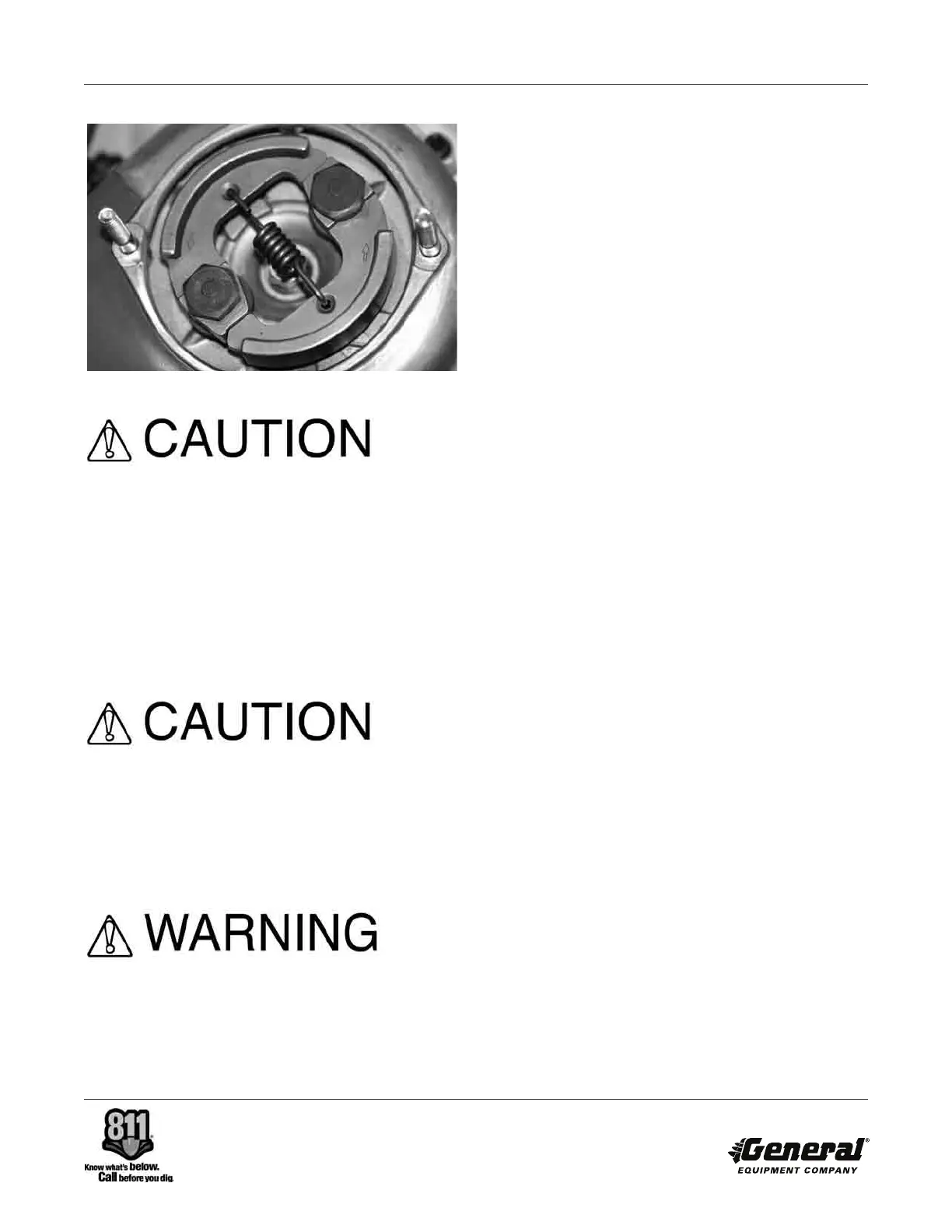
FIGURE 19
Improper orientation will result in increased
slippage, reduced digging capacity with increased
clutch wear.
11) Install the retaining shoulder bolts. Torque the
shoulder bolts to 5.4-7.2 ft. lbs. (7.5-10 N.m.). When
properly installed and torqued, the shoulder bolts
should not thrust directly against the washers and thus
apply a direct force against the clutch shoes. Such an
occurrence will restrict the proper movement of the
clutch shoes.
Improper shoulder bolt clearance will limit proper
movement of the clutch shoes and overall
operation. Such an occurrence can result in
property damage and/or personal injury.
12) Reinstall the engine to the transmission with the
correct orientation to the operator handle.
IMPROPER ENGINE MOUNTING ORIENTATION TO
THE OPERATOR HANDLE CAN REDUCE MACHINE
CONTROL DURING THE HOLE DIGGING
PROCESS. SUCH OCCURRENCE CAN RESULT IN
P RO P E R T Y DA M AG E A N D / O R P E R S O N A L
INJURY.
13) Using the wrench, tighten the 1/4 inch K-lock type
nuts. There is not adequate space to allow the use of a
conventional torque wrench. Tighten the nuts to
approximate a 90 inch pound (10 N.m.) value. An
approximate value will place the nut flush with the end
of the mounting studs.
14) Rotate the final driveshaft and check for excessive
noise and/or binding. If excessive noise and/or binding
is evident, disassemble the engine from the
transmission and investigate for probable causes.
Reassemble and retorque to the specified values.
Recheck again for excessive noise and/or binding.
15) Refill the engine fuel tank and crankcase with the
appropriate fluids as required.
16) If placing the machine back in service, follow the
procedures as outlined in this manual for starting the
engine. Refer to STARTING THE ENGINE WITH THE
AUGER CONNECTED TO THE TRANSMISSION
DRIVESHAFT.
CENT RIFUGAL CL U TCH DRUM AND P INION
SHAFT REMOVAL AND INSTALLATION.
Application: 240H Hole Digger powered by the
Honda GX35 engine.
Tools Required:
2 each, 7/16 inch wrenches
1each, plastic hammer
1 each, powered impact wrench with 12 point, 25/32
inch socket
1 each, torque wrench,120 inch pounds (13.5 N.m.)
capacity.
Parts Required:
1 each, PN 240-0100 gasket
1 each, PN 240-0160 clutch drum and pinion shaft
assembly
1 each, PN 210-0320 pinion gear (if required)
1 each, container of thread anti-seize.
1) Drain the fuel from the fuel tank and oil from the
engine crankcase into UL
®
approved containers. Wipe
any excess spilled liquids and dispose of properly.
240H ONE MAN HOLE DIGGER
FORM GOM14081201, VERSION 1.1
37