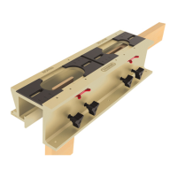
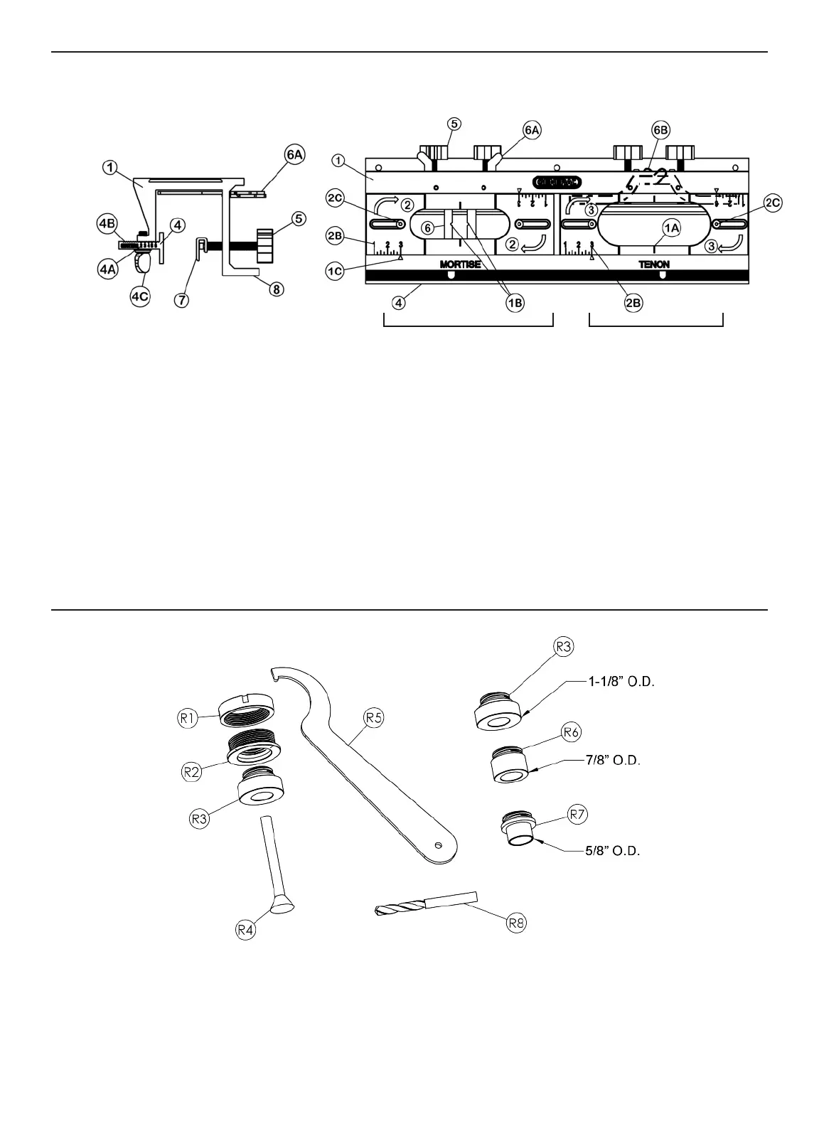
ANATOMY OF THE E-Z PRO MORTISE & TENON JIG
Fig. 1
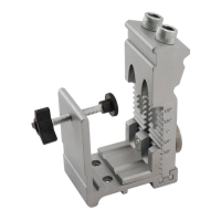
ANATOMY OF THE “QUICK CHANGE” ROUTER BASE
BUSHING ASSEMBLY:
Fig. 2
4
MORTISE SECTION
TENON SECTION
1 - Jig Assembly
1A - Centering Marks
1B - Centering Notches
1C - Template Positioning Indicators
2 - Mortise Section Templates
2B - Template Position Rule
2C - Template Lock Screws
3 - Tenon Section Templates
4 - Centering Wall, [4A] Markings,
[4B] Serrations, [4C] Thumb Screws
5 - Face Clamp Thumb Screws
6 - Positioning Bars
6A - Positioning Bars deployed
6B - Positioning Bars retracted for storage
and cutting
7 - Face Clamps
8 - Mounting Flange
R1 - Lock Nut
R2 - 1-3/16" Router Base Guide Sleeve
R3 - 1-1/8" O.D. Router Guide Bushing for
the 1/4" Tenon (as well as for all
mortises)
R4 - Centering Pin
R5 - Flat Spanner Wrench
R6 - 7/8" O.D. Router Guide Bushing
for the 3/8" Tenon
R7 - 5/8" O.D. Router Guide Bushing
for the 1/2" Tenon
R8 - 1/4" Upcut Routing Bit
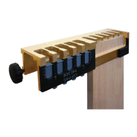
JIG ASSEMBLY
J
IG ASSEMBLY IN PROFILE