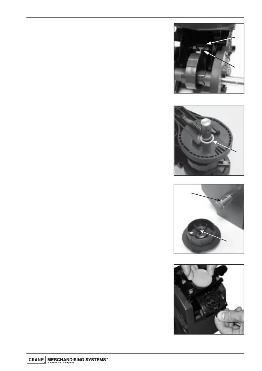
10. Check and ensure that the lower piston
guide block (c) locates with the piston drive
cam (d) as shown in the photograph.
11. Ensure that the plastic washer (a) is fitted
correctly over the input shaft (long side) as
shown.
Re-assemble the front and rear brewer
panels to the central piston chamber/swing
arms assembly using the three retaining
screws/locknuts.
Check and ensure that the brewer release
lever mechanism operates correctly.
12. Re-fit the brewer drive coupling to the input
shaft ensuring that the raised ‘pip’ (b) lines up
with its locating dimple (c) on the input shaft.
Ensure that the captive lock nut is retained in
the plastic drive coupling moulding. Using a
3mm allen key, refit the bolt to secure the
brewer drive coupling to the input shaft.
13. Take the new filter head assembly from the
service kit.
Holding the new filter assembly as shown,
turn the green locking ring anti-clockwise to
its open position, indicated by the two
arrows.
Place the filter unit up into the filter holder
and turn the green locking ring clockwise to
lock it into place.
c
d
Technical Manual
131
 Loading...