ADMA 3.0
USER MANUAL
Document Revision 2.01 | 2021 Page 71/137
9.7 Signal In
The Signal In Ports of the ADMA can be used as:
• Synchronization input to receive clock signals from an external data recording or measurement
system to permit offline synchronization with other data sources. Note: This input only
registers one pulse per ADMA cycle. Additional pulses occurring within an ADMA cycle are
ignored.
• External Trigger input to receive sporadic signals such as those from light barriers, alley
entrance, brake pedal triggers, etc..
Note: This input only registers one pulse per ADMA cycle. Additional pulses occurring within
an ADMA cycle are ignored.
• Analog input to measure analog Voltages.
• Event input to reset the ADMA distance travelled signal. (Available at IN3 only)
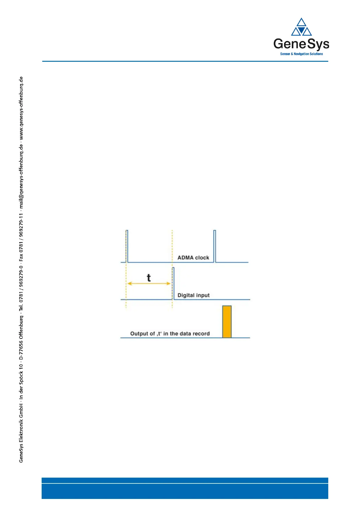
9.7.1 Functional description
The rising edge of the signal fed to the digital input triggers a time measurement. Therefore, it uses
the last ADMA sampling time point as a reference. The occurrence of this event is indicated in the
system status. The time values can be viewed in the data packet designated "Trigger times".
Figure 53 Signal IN – Trigger time
 Loading...