Measurement data
10.1 Utilised Coordinate Systems
10.2 Generalities to the utilised coordinate systems
Applicable to the coordinate systems used in ADMA (except for the positions):
• They are right-handed Cartesian coordinate systems
• Direction of rotation by the positive axis direction follows the "right hand rule"
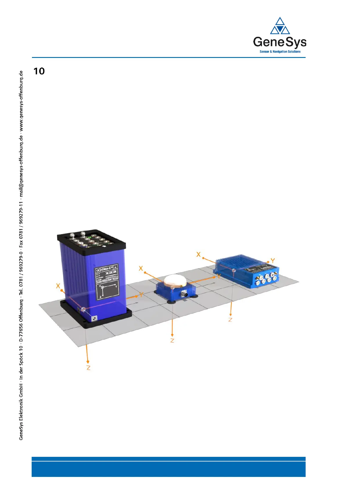
10.2.1 The ADMA measuring axis coordinate system
The type label of the ADMA shows the alignment of the measuring axes of the ADMA relative to the
housing. The X axis, as shown on the type label on the right, points away from the observer.
If the measuring axes of the gyro system as shown on the type label are aligned parallel to the axes
of the body coordinate system of the vehicle, then both coordinate systems correspond.
The aim of every setup should be that both coordinate systems overlap (measuring axes ADMA and
the body coordinate system) which can be accomplished using the corresponding assembly and by
compensation through the fitting position offset.
Figure 57 ADMA-Family measuring axis coordinate systems


 To Next Page