USB 3.0 Hub Design Guide
© 2015 Genesys Logic, Inc. - All rights reserved. Page 6
GLI Confidential
1. INTRODUCTION
The purpose of this document is to provide suggestions for the design of circuit and PCB layout regarding the
USB 3.0 Hub Controllers of Genesys Logic Inc.
2. CIRCUIT DESIGN AND PCB LAYOUT GUIDELINES
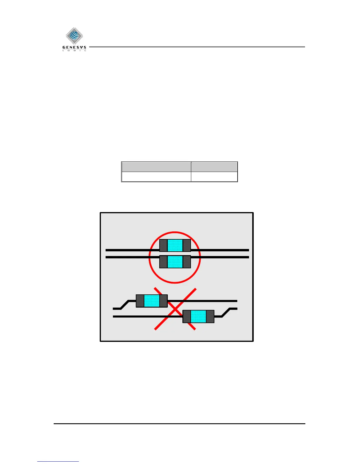
2.1 AC Coupling Capacitors
PHY is a component where the transmitter and receiver are located and operated together. The AC coupling
capacitors are associated with the transmitter.
The AC coupling Capacitor should be placed by closing to Connector. The capacitor body size should be less
than or equal to 0603 (0402 is recommended). And AC coupling capacitor must be placed symmetrically. (as
shown in Fig. 2.1)