USB 3.0 Hub Design Guide
© 2015 Genesys Logic, Inc. - All rights reserved. Page 8
GLI Confidential
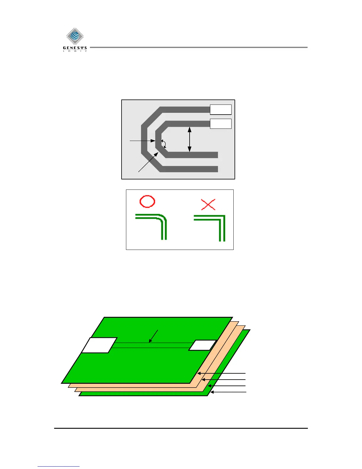
2.3.4 Trace Bend
When traces are encountered, please use 45
bends (or turns) of traces. The inner air gap of a bend, A should
be
≧
20 mils and the angles between traces should be greater than 135 degrees. (
135
) and the length of
B and C should be minimized.
Figure 2.2
2.3.5 Reference Plane
Make sure that the differential trace layer and adjacent layer are with solid GND plane.
The differential pair trace must be kept in the outer layer, and have a continual full ground plane at neighbor
layer for reference. (See Fig. 2.3)
Figure 2.3