USB 3.0 Hub Design Guide
© 2015 Genesys Logic, Inc. - All rights reserved. Page 9
GLI Confidential
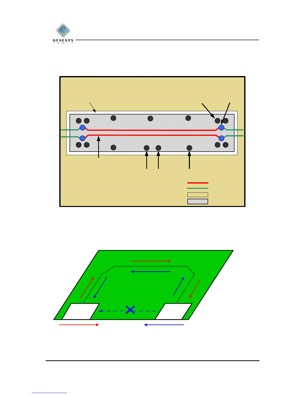
A differential pair should avoid discontinuation in the reference plane, such as splits and voids. When a
signal need changes layers, must keep the same reference plane and the ground stitching via should be
placed by closing to the signal via. A minimum of 2 stitching via per pair of signals is recommended. Never
route a trace so that it straddles a plane split. (See Fig. 2.4)
Power Plane
Ground Island
L3 Vcc layer
Differential pair at Bottom layer
Signal Via
Place Stitching Vias close to Signal Via
(Space within <= 50 mils)
Place Stitching Vias to Ground layer along edge of Ground island
Plane void
Bottom Signal
Top Signal
Layer3 Power Plane
Layer3 Ground Island
Figure 2.4
2.3.6 Signal Return Path
An incorrect signal return path is one of the most common sources for noise coupling and EMI problems.
Figure 2.5 Return Current tries to follow the Signal Path
Signal Return Path: Sink to Source